Sony RDR-HX900 Operating Instructions - Page 19
Step 4: Connecting the Audio Cords
 |
UPC - 027242644328
View all Sony RDR-HX900 manuals
Add to My Manuals
Save this manual to your list of manuals |
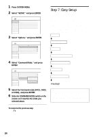
Page 19 highlights
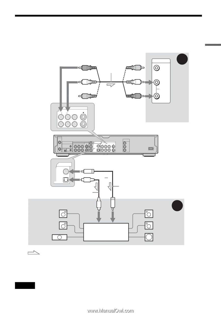
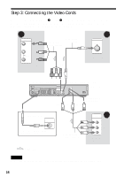
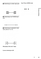
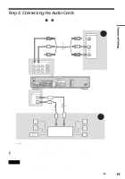
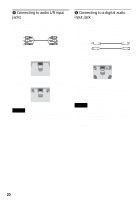
Hookups and Settings Step 4: Connecting the Audio Cords Select one of the following patterns A or B, according to the input jack on your TV monitor, projector, or AV amplifier (receiver). This will enable you to listen to sound. (red) (white) Audio/video cord (supplied) (yellow) (white) (yellow)* (red) INPUT A VIDEO L AUDIO R LINE OUT 1 R AUDIO L VIDEO S VIDEO 2 TV, projector, or AV amplifier (receiver) to LINE OUT (R-AUDIO-L) 1 or 2 VHF/UHF IN SET TOP BOX CONTROL COMPONENT VIDEO IN LINE IN R AUDIO L VIDEO S VIDEO OUT 1 G-LINK 3 CONTROL S IN DIGITAL OUT Y PCM/DTS/DOLBY DIGITAL LINE OUT COAXIAL 1 R AUDIO L VIDEO PB 2 PR OPTICAL S VIDEO COMPONENT VIDEO OUT Y PB PR ~ AC IN DIGITAL OUT PCM/DTS/DOLBY DIGITAL COAXIAL to DIGITAL OUT (COAXIAL or OPTICAL) DVD recorder or OPTICAL Optical digital cord (not supplied) Coaxial digital cord (not supplied) [Speakers] Rear (L) Front (L) Center to optical digital input to coaxial digital input AV amplifier (receiver) with a decoder B [Speakers] Rear (R) Front (R) Subwoofer : Signal flow * The yellow plug is used for video signals (page 17). z Hint For correct speaker location, see the operating instructions supplied with the connected components. Note Do not connect your TV's audio output jacks to the LINE IN (AUDIO L/R) jacks at the same time. This will cause unwanted noise to come from your TV's speakers. ,continued 19
-
 1
1 -
2
-
3
-
4
-
5
-
6
-
7
-
8
-
9
-
10
-
11
-
12
-
13
-
 14
14 -
 15
15 -
 16
16 -
 17
17 -
 18
18 -
 19
19 -
 20
20 -
 21
21 -
 22
22 -
 23
23 -
 24
24 -
25
-
26
-
27
-
28
-
29
-
30
-
31
-
32
-
33
-
34
-
35
-
36
-
37
-
38
-
39
-
40
-
41
-
42
-
43
-
44
-
45
-
46
-
47
-
48
-
49
-
50
-
51
-
52
-
53
-
54
-
55
-
56
-
57
-
58
-
59
-
60
-
61
-
62
-
63
-
64
-
65
-
66
-
67
-
68
-
69
-
70
-
71
-
72
-
73
-
74
-
75
-
76
-
77
-
78
-
79
-
80
-
81
-
82
-
83
-
84
-
85
-
86
-
87
-
88
-
89
-
90
-
91
-
92
-
93
-
94
-
95
-
96
-
97
-
98
-
99
-
100
-
101
-
102
-
103
-
104
-
105
-
106
-
107
-
108
-
109
-
110
-
111
-
112
-
113
-
114
-
115
-
116
-
117
-
118
-
119
-
120
 |
 |