Yamaha N12 Owners Manual - Page 11
Inside Your Mixer, Basic Structure - recording
 |
UPC - 086792859866
View all Yamaha N12 manuals
Add to My Manuals
Save this manual to your list of manuals |
Page 11 highlights
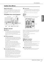
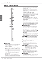
Inside Your Mixer Basic Structure The purpose of configuring an audio system around a mixer is to collect signals from all channels and mix to achieve a good balance. Here is a greatly simplified block diagram of a mixer to help you understand the signal path. Simplified mixer block diagram input channel master bus section Recording Basics 4 Channel fader A channel fader enables you to adjust the level of the corresponding input channel signal that is going to be routed to the buses (excluding a pre-fader signal). This control is most often used during mixing. ■ Bus 5 Bus Input channel signals are routed to buses, mixed together there, then output in stereo (master). BUS English IN COMP EQ OUT bus 1 2 34 5 67 ■ Input channel 1 Head amp The very first stage in any mixer through which the input signal flows. The head amp features a gain control that enables you to adjust the mixer's input sensitivity to match the level of the source. You can amplify small signals, and attenuate large signals. 2 Compressor/Equalizer This stage enables you to process the input signal. A compressor attenuates the peak level of the input signal, and raises the overall signal level at the same time, to lessen the level difference and raise the sound pressure. An equalizer adjusts the tone by boosting (amplifying) or cutting (attenuating) certain frequency ranges. You can use an equalizer to change the tone to suit the acoustic environment of a particular room, or to create a new sound. An equalizer could be a high pass filter that cuts the sound below a specified frequency. Some mixers feature compressors and/or equalizers, and some do not. 3 Level meter (input channel) If the signal level is too high for the head amp or compressor/equalizer to handle, the sound will clip and be distorted. An input channel level meter enables you to monitor this signal level. Some mixers feature a channel peak LED that indicates only the peak level. If the input signal is overloaded, adjust the head amp gain control. Most mixers have multiple level meters (including the indicators). It is important to know the mixer stage for which the meters are indicating signal levels. Buses are categorized into a few types based on their purpose: stereo bus for stereo mix, AUX bus for AUX send, etc. Using the appropriate buses is one of the keys to basic mixing. The n8/n12 features the following buses: • STEREO bus (L/R) • AUX bus (L/R) • REC bus (L/R) • REVERB bus (L/R) • SOLO bus (L/R) ■ Master section 6 Stereo (master) fader The master section enables you to adjust the level of signals routed from buses. Use a stereo master fader to adjust the level of the mixer's main output from the stereo buses. Depending on the design of the mixer, a fader is provided for each bus so that you can adjust the level of each bus output. 7 Level meter (master) This meter indicates the signal level in the master section, which is the mixer's final output level. Owner's Manual 11
-
 1
1 -
2
-
3
-
4
-
5
-
 6
6 -
 7
7 -
 8
8 -
 9
9 -
 10
10 -
 11
11 -
 12
12 -
 13
13 -
 14
14 -
 15
15 -
 16
16 -
17
-
18
-
19
-
20
-
21
-
22
-
23
-
24
-
25
-
26
-
27
-
28
-
29
-
30
-
31
-
32
-
33
-
34
-
35
-
36
-
37
-
38
-
39
-
40
-
41
-
42
-
43
-
44
-
45
-
46
-
47
-
48
-
49
-
50
-
51
-
52
-
53
-
54
-
55
-
56
-
57
-
58
-
59
-
60
-
61
-
62
 |
 |
