Yamaha N12 Owners Manual - Page 15
SOLO] switch, Channel [ON] switch, Channel fader, Input meter, WET] switch, REC] switch and [ST] - case
 |
UPC - 086792859866
View all Yamaha N12 manuals
Add to My Manuals
Save this manual to your list of manuals |
Page 15 highlights
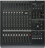
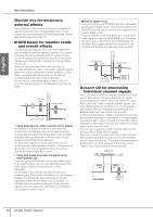
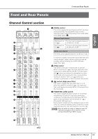
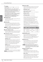
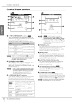
English # [SOLO] switch This switch turns the Solo function on and off. Turn this switch on (the switch LED lights up), if you want to listen to certain channels without changing the mix contents or signal path. NOTE If you switch the monitor source by using the [C-R SOURCE SELECT] switch (page 18), all channel [SOLO] switches will be reset to off. $ Channel [ON] switch Switches each channel on and off. If you turn the switch on, the channel signal will be sent to each bus. When the switch is turned off (the switch indicator turns off), the channel signal will be sent only to the AUX bus. NOTE Direct output to a connected computer is always available regardless of the channel [ON] switch status. % Channel fader The channel fader adjusts the input channel signal level. The fader at the "0" position corresponds to the nominal output level. This means that the prefader level and post-fader level are identical. ^ Input meter The four LEDs indicate the input channel signal level. When the input signal is clipping, the OVER LED will light up. Only You can check the level of the post-fader signal via the input meter by setting the [INPUT METER] switch (page 17) in the Meter section to "POST." & [WET] switch This switch determines whether or not the input channel monitor signal will be processed via the Monitor Remote function. If you turn this switch on (the LED lights up) while Cubase and the mixer are linked and operating together, you can monitor a wet signal (an input signal that has been processed via the VST or other effects). NOTE • While this switch is turned on, the [AUX] control for the corresponding input channel will be disabled. • To use the Monitor Remote function, you must turn on the MONITOR REMOTE [ON] switch (page 19) (the switch LED will light up). * [REC] switch and [ST] switch These switches route the signal to the specified buses. Turn the [ST] switch on (the LED lights up) to route the channel signal to the stereo L/R buses. Turn the [REC] switch on to route the channel signal to the REC (L/R) buses. Front and Rear Panels Tip for compensating for the phase offset When you are recording a single instrument using multiple microphones, the position and the distance between the instrument and microphones may cause the phase of each recorded signal to be offset against each other (out of phase). If you try to mix such signals, the signals will interfere with each other, resulting in a thin sound. For example if you record the sound of a guitar amplifier by placing microphones in front of and behind it in order to capture the resonance of the cabinet, the microphone placed behind the amplifier will pick up a signal with an offset phase. In this case, turn the [PHASE] switch (5) on to avoid the phase offset and interference. phase of mic signal from behind phase offset phase of mic signal from in front Owner's Manual 15
-
 1
1 -
2
-
3
-
4
-
5
-
6
-
7
-
8
-
9
-
 10
10 -
 11
11 -
 12
12 -
 13
13 -
 14
14 -
 15
15 -
 16
16 -
 17
17 -
 18
18 -
 19
19 -
 20
20 -
21
-
22
-
23
-
24
-
25
-
26
-
27
-
28
-
29
-
30
-
31
-
32
-
33
-
34
-
35
-
36
-
37
-
38
-
39
-
40
-
41
-
42
-
43
-
44
-
45
-
46
-
47
-
48
-
49
-
50
-
51
-
52
-
53
-
54
-
55
-
56
-
57
-
58
-
59
-
60
-
61
-
62
 |
 |
