Yamaha N12 Owners Manual - Page 16
Master Control Reverb TR TO ST STEREO [BAL] control
 |
UPC - 086792859866
View all Yamaha N12 manuals
Add to My Manuals
Save this manual to your list of manuals |
Page 16 highlights
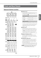
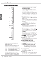
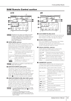
English Front and Rear Panels Master Control section 1 2 3 4 5 6 7 1 Reverb section This section enables you to set the type, output level, and other settings for the internal digital reverb. REVERB [TYPE] switch This switch determines the type of internal digital reverb. Each press of the switch cycles through different effect types in this order: HALL → ROOM → PLATE. HALL ROOM Simulates reverberation in a concert hall. Simulates reverberation in a room. PLATE Simulates reverberation of a plate echo. [REVERB TIME] control This control adjusts the reverb time (duration of reverberation) of the internal digital reverb. Rotating the knob counter-clockwise will shorten the duration, 16 Owner's Manual and rotating it clockwise will extend the duration. REVERB [LEVEL] control This control adjusts the output level of the internal digital reverb. The "▼" position corresponds to the nominal level (0 dB). [TO AUX]/[TO REC]/[TO ST] switches These switches route the output signal from the internal digital reverb to the AUX, REC, or STEREO buses. Turn the desired switch on ( ) to route the output from the internal digital reverb to the desired buses. 2 2TR TO ST section This section enables you to adjust the level of and route the signal input from the 2TR IN jacks (page 20). [LEVEL] control Adjusts the level of the signal input from the 2TR IN jacks. The "▼" position corresponds to the nominal level (0 dB). [ON] switch This switch determines whether the 2TR IN signal will be sent to the STEREO buses. When the switch is turned on ( ), the 2TR IN signal is sent to the stereo buses. 3 DAW TO ST section This section enables you to adjust the level of and route the stereo signal transmitted from the DAW (DAW IN 1/2). [LEVEL] control This control adjusts the level of the stereo DAW signal to the STEREO buses. The knob set to the "▼" position corresponds to the nominal level (0 dB). [ON] switch This switch determines whether the stereo output signal from the DAW will be routed to the STEREO buses. When the switch is turned on ( ), the stereo output from the DAW will be sent to the mixer's STEREO buses. NOTE Only If you turn on the C-R SOURCE SELECT [5.1] switch, the DAW TO ST [ON] switch will be disabled (the switch indicator will flash). 4 STEREO [BAL] control This control adjusts the left and right volume balance of the stereo channels (STEREO L/R). 5 [PFL] (Pre-Fader Listen) switch If you want to monitor pre-fader input channel signals when you are using the Solo function, turn this switch on ( ). NOTE Only While this switch is turned on, if you also turn the [SOLO] switch on, the monitor signal volume may become very loud. In this case, use the [SOLO LEVEL] control (page 17) to adjust the monitoring volume level. The monitoring volume level of the n8 is always attenuated by 12 dB. 6 STEREO [ON] switch This switch turns on and off the signal output from the ST OUT jacks. When the switch is on ( ), the signal is output from the ST OUT jacks. 7 STEREO fader This fader adjusts the level of the signal output from the ST OUT jacks. The "0" position corresponds to the nominal output level (0 dB).
-
 1
1 -
2
-
3
-
4
-
5
-
6
-
7
-
8
-
9
-
10
-
 11
11 -
 12
12 -
 13
13 -
 14
14 -
 15
15 -
 16
16 -
 17
17 -
 18
18 -
 19
19 -
 20
20 -
 21
21 -
22
-
23
-
24
-
25
-
26
-
27
-
28
-
29
-
30
-
31
-
32
-
33
-
34
-
35
-
36
-
37
-
38
-
39
-
40
-
41
-
42
-
43
-
44
-
45
-
46
-
47
-
48
-
49
-
50
-
51
-
52
-
53
-
54
-
55
-
56
-
57
-
58
-
59
-
60
-
61
-
62
 |
 |
