Yamaha N12 Owners Manual - Page 14
PHASE] switch, Hi-Z] switch, INPUT SELECT] switch, Compressor controls, Equalizer EQ, REVERB] control - cubase 5
 |
UPC - 086792859866
View all Yamaha N12 manuals
Add to My Manuals
Save this manual to your list of manuals |
Page 14 highlights
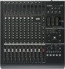
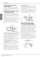
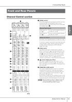
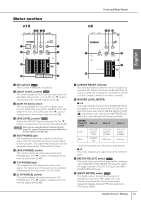
Front and Rear Panels English Caution • Be sure to leave this switch off ( ) if you do not need phantom power. • When turning the switch on ( ), make sure that only condenser microphones are connected to the INPUT A jacks. Devices other than condenser microphones may be damaged if they are connected to the phantom power supply. Note, however, that the switch may be left on when you connect balanced dynamic microphones. • To avoid damage to your hearing or speakers, be sure to roll off the volume level of the amplifier (or powered speakers) before turning this switch on or off. Yamaha also recommends that you turn all output controls, such as the STEREO fader and [C-R PHONES LEVEL] control to minimum settings before operating the switch. 5 [PHASE] switch Turning this switch on ( ) inverts the phase of the signal from the input jacks. For more information on the [PHASE] switch, refer to the next page. 6 [Hi-Z] switch If you are connecting an electric guitar or electric bass that has passive-type pickups and no built-in preamp directly to the INPUT B jack of input channel 8 (on the n12) or input channel 4 (on the n8), turn this switch on ( ). NOTE Use an unbalanced cable when you connect an electric guitar or bass and turn the [Hi-Z] switch on. If you use a balanced cable, the mixer will not work correctly. 7 [INPUT SELECT] switch This switch determines whether the input jack signal (A.IN) or the DAW signal (the output from Cubase or another DAW) will be routed to the input channels. 8 Compressor controls These compressor controls enable you to operate the compressor for each monaural input channel (channels 1-4 on the n8, and channels 1-8 on the n12). The following two controls are available for each compressor: [MORPH] control and [DRIVE] control. [MORPH] control This control specifies the compressor setting. Knob positions A-E correspond to different presets. You can easily change the compressor setting by rotating the control. Knob positions between alphabetical settings will use an intermediate value taken from between two corresponding preset values. [DRIVE] control This control specifies the amount of compression. As you rotate the control clockwise, more compression is applied. The output level changes automatically as the amount of compression changes. COMP LED This LED lights up when the compressor is triggered. NOTE For more information on how to use the compressor, please refer to page 28. 14 Owner's Manual 9 Equalizer (EQ) This three-band equalizer adjusts the input channel's high, mid, and low frequency bands. You can also adjust the center frequency for the mid band. [HIGH] gain control This control adjusts the high band gain. [MID] frequency control This control adjusts the mid band center frequency. [MID] gain control This control adjusts the mid band gain. [LOW] gain control This control adjusts the low band gain. Setting each gain control knob to the (▼) position produces a flat frequency response (no boost). Turning the knob clockwise boosts the corresponding frequency band, while turning counter-clockwise attenuates the band. To raise the mid band center frequency, turn the [MID] frequency control clockwise. To lower the center frequency, turn the [MID] frequency control counter-clockwise. At the center position, the center frequency is 1.0 kHz. The following table shows the EQ type, center frequency, and maximum cut/boost for each of the three bands. Band HIGH MID LOW Type Center Frequency shelving peaking shelving 10 kHz 100 Hz - 10 kHz 90 Hz Maximum Cut/Boost ±18 dB ±18 dB ±18 dB ) [REVERB] control This control adjusts the level of the input channel signal sent to the internal digital reverb (i.e., determines how much reverb will be applied). When you set the knob to the (▼) position, the input channel signal at the nominal level (0 dB) will be sent to the internal digital reverb. ! [AUX] control This control adjusts the level of the input channel signal sent to the AUX bus. Use this control when you are sending a mix monitoring signal to the musicians, or sending the signal to an external device, such as an effects processor. NOTE While the Monitor Remote function (page 33) is in effect, signals that pass through a DAW will be directly routed to the AUX bus. Therefore, the [AUX] control will be temporarily disabled while the [WET] switch is turned on. @ [PAN] and [BAL] controls [PAN] control This control determines the stereo position of the monaural input channel. Rotate the knob clockwise to pan the signal right, and counter-clockwise to pan left. [BAL] control This control determines the volume balance between the left and right stereo channels. Odd channel signals are fed to the L bus, and even channel signals are fed to the R bus. For example, rotate the [BAL] control all the way to right to output only the even (right) channel signals.
-
 1
1 -
2
-
3
-
4
-
5
-
6
-
7
-
8
-
 9
9 -
 10
10 -
 11
11 -
 12
12 -
 13
13 -
 14
14 -
 15
15 -
 16
16 -
 17
17 -
 18
18 -
 19
19 -
20
-
21
-
22
-
23
-
24
-
25
-
26
-
27
-
28
-
29
-
30
-
31
-
32
-
33
-
34
-
35
-
36
-
37
-
38
-
39
-
40
-
41
-
42
-
43
-
44
-
45
-
46
-
47
-
48
-
49
-
50
-
51
-
52
-
53
-
54
-
55
-
56
-
57
-
58
-
59
-
60
-
61
-
62
 |
 |
