Yamaha N12 Owners Manual - Page 17
Meter DAW TO AUX] control - cubase 6
 |
UPC - 086792859866
View all Yamaha N12 manuals
Add to My Manuals
Save this manual to your list of manuals |
Page 17 highlights
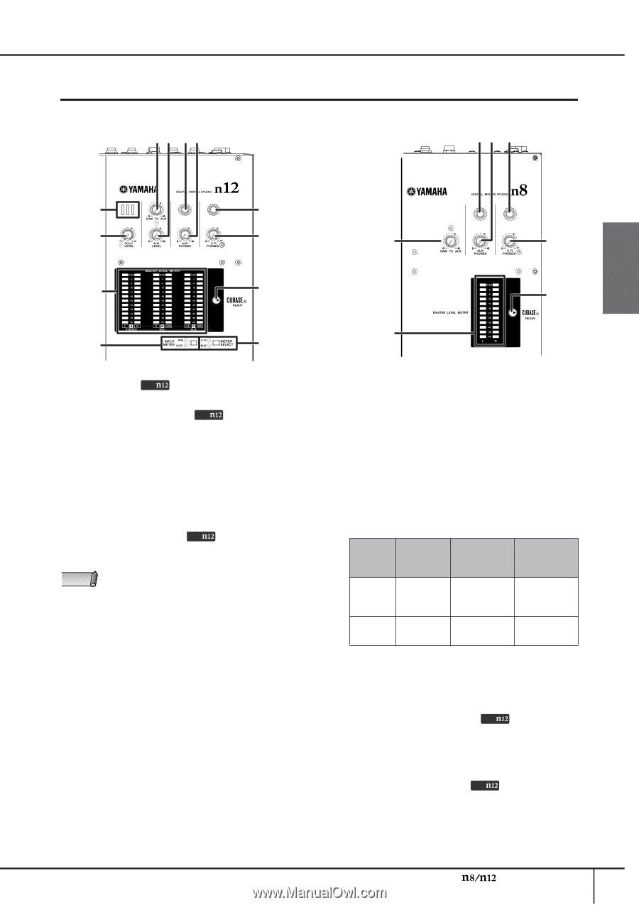
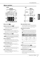
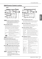
Meter section n12 34 56 Front and Rear Panels n8 56 7 English 1 7 2 8 3 8 ) 9 9 ) @ ! 1 Microphone Only This is a built-in talkback microphone. 2 [SOLO LEVEL] control Only This control adjusts the SOLO L/R bus output level. The adjustable range is from -∞ to +6 dB. The "▼" position corresponds to the nominal output level (0 dB). 3 [DAW TO AUX] control This control adjusts the level of the signal routed from the DAW AUX output (n12= DAW IN 15/16, n8= DAW IN 11/12) to the AUX buses. The "▼" position corresponds to the nominal output level (0 dB). 4 [AUX LEVEL] control Only Adjusts the AUX OUT signal level (page 21). The "▼" position corresponds to the nominal output level (0 dB). NOTE While you are using the Monitor Remote function (page 33), signals that pass through the DAW will be directly routed to the AUX bus. 5 AUX PHONES jack This headphone connector outputs the AUX bus signal. Use this connector to send a monitor signal to the musicians. The output level at this jack can be adjusted independently of the AUX OUT jacks. 6 [AUX PHONES] control This control adjusts the output level at the AUX PHONES jack. The "▼" position corresponds to the nominal output level (0 dB). 7 C-R PHONES jack This headphone jack outputs the control room signal. The output level at this jack can be adjusted independently from that of the C-R OUT jacks. 8 [C-R PHONES] control This control adjusts the output level at the C-R PHONES jack. The "▼" position corresponds to the nominal output level (0 dB). 9 CUBASE READY indicator This indicator lights up when the mixer is ready to be operated with Cubase 4/Cubase Studio 4/Cubase AI 4; that is, when the computer is connected to the n8/ n12 and Cubase is linked to the mixer correctly. ) MASTER LEVEL METER ■ n12 This meter indicates the level of the STEREO/REC/AUX bus signals, or the output level at the C-R OUT jack. To switch the meter view, use the [METER SELECT] switch (!). Depending on the setting of the [METER SELECT] switch, the meter indication will change as follows: [METER SELECT] switch C-R* BUS Meter A C-R OUT jacks A (L/R) STEREO bus Meter B C-R OUT jacks B (C/SW) REC bus Meter C C-R OUT jacks C (LS/RS) AUX bus * Surround channels are indicated in parentheses. ■ n8 This meter indicates the output level at the C-R OUT jacks. ! [METER SELECT] switch Only This switch determines which signal will be indicated via the MASTER LEVEL METER. Pressing the switch will toggle between C-R (C-R OUT jacks) and BUS (STEREO/REC/AUX bus). @ [INPUT METER] switch Only This switch selects the signal whose level is indicated on the input meter (page 15) in the Channel Control section. Pressing the switch repeatedly toggles between PRE (pre-fader) and POST (post-fader). Owner's Manual 17
-
 1
1 -
2
-
3
-
4
-
5
-
6
-
7
-
8
-
9
-
10
-
11
-
 12
12 -
 13
13 -
 14
14 -
 15
15 -
 16
16 -
 17
17 -
 18
18 -
 19
19 -
 20
20 -
 21
21 -
 22
22 -
23
-
24
-
25
-
26
-
27
-
28
-
29
-
30
-
31
-
32
-
33
-
34
-
35
-
36
-
37
-
38
-
39
-
40
-
41
-
42
-
43
-
44
-
45
-
46
-
47
-
48
-
49
-
50
-
51
-
52
-
53
-
54
-
55
-
56
-
57
-
58
-
59
-
60
-
61
-
62
 |
 |