Acer G540-E5405 Altos G540 User's Guide EN - Page 134
Vertical mounting hole pattern, The distance from the center of two holes with closer spacing to
 |
UPC - 750519186893
View all Acer G540-E5405 manuals
Add to My Manuals
Save this manual to your list of manuals |
Page 134 highlights
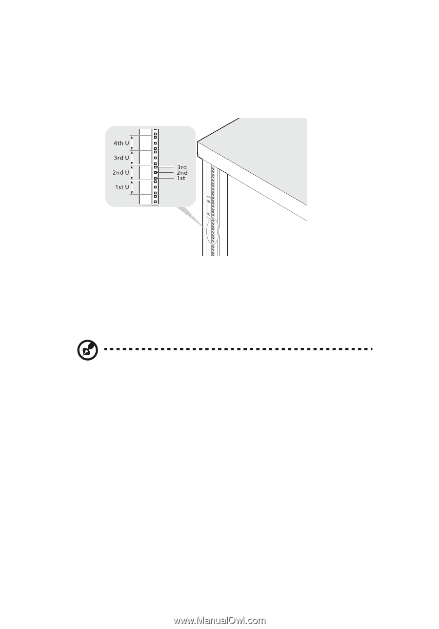
124 Appendix B: Rack mount configuration Vertical mounting hole pattern The four vertical rails of the system rack contain mounting holes arranged in a manner shown in the figure below. The system occupies 5U in the rack. Count the U positions and hole numbers from the bottom up. The distance from the center of two holes with closer spacing to the center of the next pair is equivalent to 1U. Note: The unit of measurement used in this guide is "U" (1U = 1.75 inches or 44.45 mm). The total sum of the heights of all components in the rack measured in "U" cannot exceed the height of the rack. For more information, refer to the documentation that came with the system rack. When installing components, you must start your measurement from the center of the two holes with closer spacing. Otherwise, the screw holes on the component may not match those on the rack.
-
 1
1 -
2
-
3
-
4
-
5
-
6
-
7
-
8
-
9
-
10
-
11
-
12
-
13
-
14
-
15
-
16
-
17
-
18
-
19
-
20
-
21
-
22
-
23
-
24
-
25
-
26
-
27
-
28
-
29
-
30
-
31
-
32
-
33
-
34
-
35
-
36
-
37
-
38
-
39
-
40
-
41
-
42
-
43
-
44
-
45
-
46
-
47
-
48
-
49
-
50
-
51
-
52
-
53
-
54
-
55
-
56
-
57
-
58
-
59
-
60
-
61
-
62
-
63
-
64
-
65
-
66
-
67
-
68
-
69
-
70
-
71
-
72
-
73
-
74
-
75
-
76
-
77
-
78
-
79
-
80
-
81
-
82
-
83
-
84
-
85
-
86
-
87
-
88
-
89
-
90
-
91
-
92
-
93
-
94
-
95
-
96
-
97
-
98
-
99
-
100
-
101
-
102
-
103
-
104
-
105
-
106
-
107
-
108
-
109
-
110
-
111
-
112
-
113
-
114
-
115
-
116
-
117
-
118
-
119
-
120
-
121
-
122
-
123
-
124
-
125
-
126
-
127
-
128
-
 129
129 -
 130
130 -
 131
131 -
 132
132 -
 133
133 -
 134
134 -
 135
135 -
 136
136 -
 137
137 -
 138
138 -
 139
139 -
140
-
141
-
142
-
143
-
144
-
145
-
146
 |
 |