Acer G540-E5405 Altos G540 User's Guide EN - Page 66
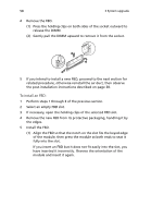
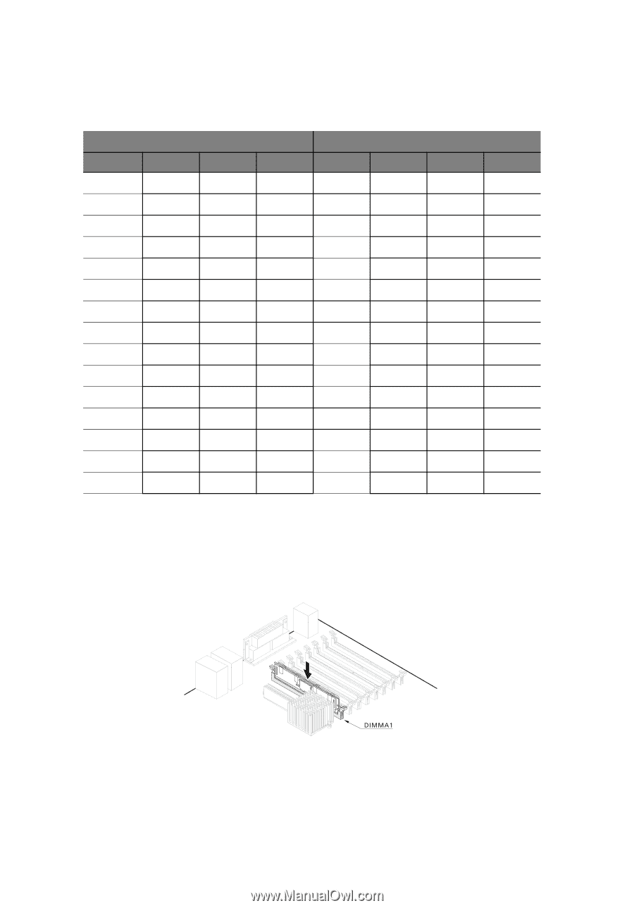
In a minimum memory configuration, the FBD should be, installed in the DIMMA1 slot. - memory upgrade
 |
UPC - 750519186893
View all Acer G540-E5405 manuals
Add to My Manuals
Save this manual to your list of manuals |
Page 66 highlights
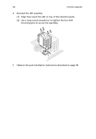
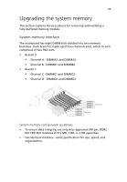
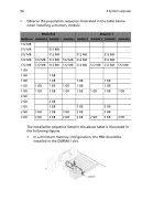
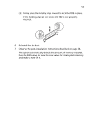
56 3 System upgrade • Observe the population sequence illustrated in the table below when installing a memory module. Branch 0 Branch 1 DIMM A1 DIMMA2 DIMMB 1 DIMMB2 DIMMC1 DIMMC2 DIMMD1 DIMMD2 512 MB 512 MB 512 MB 512 MB 512 MB 512 MB 512 MB 512 MB 512 MB 512 MB 512 MB 512 MB 512 MB 512 MB 512 MB 512 MB 512 MB 512 MB 512 MB 512 MB 512 MB 1 GB 1 GB 1 GB 1 GB 1 GB 1 GB 1 GB 1 GB 1 GB 1 GB 1 GB 1 GB 1 GB 1 GB 1 GB 1 GB 1 GB 1 GB 1 GB 1 GB 1 GB 2 GB 2 GB 2 GB 2 GB 2 GB 2 GB 2 GB 2 GB 2 GB 2 GB 2 GB 2 GB 2 GB 2 GB 2 GB 2 GB 2 GB 2 GB 2 GB 2 GB 2 GB The installation sequence listed in the above table is illustrated in the following figures. • In a minimum memory configuration, the FBD should be installed in the DIMMA1 slot.
-
 1
1 -
2
-
3
-
4
-
5
-
6
-
7
-
8
-
9
-
10
-
11
-
12
-
13
-
14
-
15
-
16
-
17
-
18
-
19
-
20
-
21
-
22
-
23
-
24
-
25
-
26
-
27
-
28
-
29
-
30
-
31
-
32
-
33
-
34
-
35
-
36
-
37
-
38
-
39
-
40
-
41
-
42
-
43
-
44
-
45
-
46
-
47
-
48
-
49
-
50
-
51
-
52
-
53
-
54
-
55
-
56
-
57
-
58
-
59
-
60
-
 61
61 -
 62
62 -
 63
63 -
 64
64 -
 65
65 -
 66
66 -
 67
67 -
 68
68 -
 69
69 -
 70
70 -
 71
71 -
72
-
73
-
74
-
75
-
76
-
77
-
78
-
79
-
80
-
81
-
82
-
83
-
84
-
85
-
86
-
87
-
88
-
89
-
90
-
91
-
92
-
93
-
94
-
95
-
96
-
97
-
98
-
99
-
100
-
101
-
102
-
103
-
104
-
105
-
106
-
107
-
108
-
109
-
110
-
111
-
112
-
113
-
114
-
115
-
116
-
117
-
118
-
119
-
120
-
121
-
122
-
123
-
124
-
125
-
126
-
127
-
128
-
129
-
130
-
131
-
132
-
133
-
134
-
135
-
136
-
137
-
138
-
139
-
140
-
141
-
142
-
143
-
144
-
145
-
146
 |
 |
3 System upgrade
56
•
Observe the population sequence illustrated in the table below
when installing a memory module.
The installation sequence listed in the above table is illustrated in
the following figures.
•
In a minimum memory configuration, the FBD should be
installed in the DIMMA1 slot.
Branch 0
Branch 1
DIMM A1
DIMMA2
DIMMB 1
DIMMB2
DIMMC1
DIMMC2
DIMMD1
DIMMD2
512 MB
512 MB
512 MB
512 MB
512 MB
512 MB
512 MB
512 MB
512 MB
512 MB
512 MB
512 MB
512 MB
512 MB
512 MB
512 MB
512 MB
512 MB
512 MB
512 MB
512 MB
1 GB
1 GB
1 GB
1 GB
1 GB
1 GB
1 GB
1 GB
1 GB
1 GB
1 GB
1 GB
1 GB
1 GB
1 GB
1 GB
1 GB
1 GB
1 GB
1 GB
1 GB
2 GB
2 GB
2 GB
2 GB
2 GB
2 GB
2 GB
2 GB
2 GB
2 GB
2 GB
2 GB
2 GB
2 GB
2 GB
2 GB
2 GB
2 GB
2 GB
2 GB
2 GB