Belkin F1DP216G User Manual - Page 13
The Server Interface Modules SIMs
 |
View all Belkin F1DP216G manuals
Add to My Manuals
Save this manual to your list of manuals |
Page 13 highlights
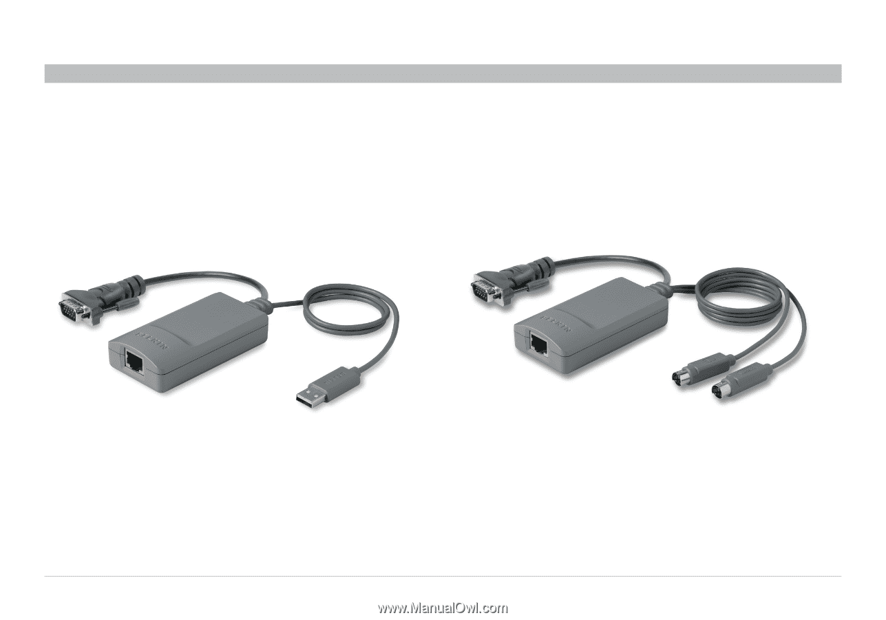
INSTALLATION Table of Contents sections 1 2 3 4 5 6 The Server Interface Modules (SIMs) Each computer/server is directly connected to the Switch via the appropriate SIM using CAT5 cables in a star configuration. No external power is needed at the remote SIMs. The SIMs draw their power from the computer's keyboard port (PS/2 SIM) or from the USB port (USB SIM). The figures below illustrate the SIM PS/2 and USB. Figure 6 USB SIM2 (part no. F1DP101A-AU) Figure 7 PS/2 SIM (part no. F1DP101A-AP) OmniViewIP 5216K/5232K 10
-
 1
1 -
2
-
3
-
4
-
5
-
6
-
7
-
 8
8 -
 9
9 -
 10
10 -
 11
11 -
 12
12 -
 13
13 -
 14
14 -
 15
15 -
 16
16 -
 17
17 -
 18
18 -
19
-
20
-
21
-
22
-
23
-
24
-
25
-
26
-
27
-
28
-
29
-
30
-
31
-
32
-
33
-
34
-
35
-
36
-
37
-
38
-
39
-
40
-
41
-
42
-
43
-
44
-
45
-
46
-
47
-
48
-
49
-
50
-
51
-
52
-
53
-
54
-
55
-
56
-
57
 |
 |
10
OmniViewIP 5216K/5232K
SECTIONS
Table of Contents
1
3
4
5
6
2
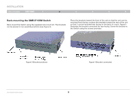
INSTALLATION
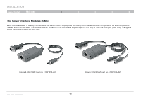
The Server Interface Modules (SIMs)
Each computer/server is directly connected to the Switch via the appropriate SIM using CAT5 cables in a star configuration. No external power is
needed at the remote SIMs. The SIMs draw their power from the computer’s keyboard port (PS/2 SIM) or from the USB port (USB SIM). The figures
below illustrate the SIM PS/2 and USB.
Figure 6 USB SIM2 (part no. F1DP101A-AU)
Figure 7 PS/2 SIM (part no. F1DP101A-AP)