Belkin F1DP216G User Manual - Page 9
Unit Display Diagrams, LED and button table, Connector table
 |
View all Belkin F1DP216G manuals
Add to My Manuals
Save this manual to your list of manuals |
Page 9 highlights
Introduction Digital Table of Contents sections 1 2 3 4 5 6 Unit Display Diagrams Figure 1 illustrates the front panel of the OmniView IP 5232K Switch. Digital Figure 1 OmniView IP 5232K Switch - front view J
-
 1
1 -
2
-
3
-
 4
4 -
 5
5 -
 6
6 -
 7
7 -
 8
8 -
 9
9 -
 10
10 -
 11
11 -
 12
12 -
 13
13 -
 14
14 -
15
-
16
-
17
-
18
-
19
-
20
-
21
-
22
-
23
-
24
-
25
-
26
-
27
-
28
-
29
-
30
-
31
-
32
-
33
-
34
-
35
-
36
-
37
-
38
-
39
-
40
-
41
-
42
-
43
-
44
-
45
-
46
-
47
-
48
-
49
-
50
-
51
-
52
-
53
-
54
-
55
-
56
-
57
 |
 |
6
OmniViewIP 5216K/5232K
SECTIONS
Table of Contents
2
3
4
5
6
1
INTRODUCTION
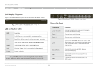
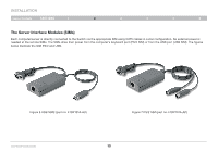
Unit Display Diagrams
Figure 1 illustrates the front panel of the OmniView IP 5232K Switch.
Figure 1 OmniView IP 5232K Switch – front view
LED and button table
LED
Function
Port
Solid: Server is connected to and powered on
Fast Blink: When a port is being accessed remotely
Slow Blink: When a port is being accessed locally
Ready
Solid Green: When unit is available for use
Link
Blinking Green: Unit is connected to the network
Power
Power Indicator
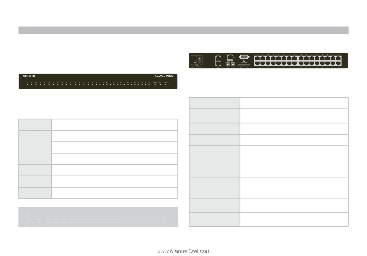
Figure 2 OmniView IP 5232K Switch – rear view
Connector table
Connector
Function
Local Console
Connect a keyboard, video, and mouse to
operate the Switch locally.
Serial 1
Connect any serial device.
Serial 2
Connect any serial device.
LAN
Connect to 10/100Mb Ethernet. Yellow LED
illuminates when connected to a LAN. Green
LED illuminates when a remote session is
in progress.
Server Ports
Connect to servers via SIMs (Server
Interface Modules).
VM1
Connect to server on server port 1 via
USB cable.
VM2
Connect to server on server port 2 via
USB cable.
Note:
The port LEDs flash in series during boot up and during
system upgrades. Allow approximately 45 seconds for boot up.