Brother International GT-361 Instruction Manual - English - Page 132
Load the Maintenance Solution first. Replace the Maintenance Cartridge to the well-shaken White Ink Cartridge and then
 |
View all Brother International GT-361 manuals
Add to My Manuals
Save this manual to your list of manuals |
Page 132 highlights
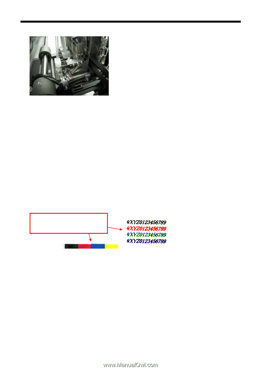
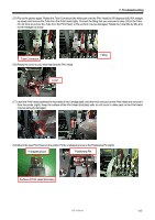
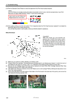
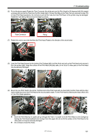
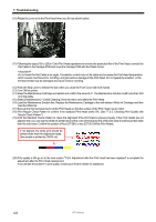
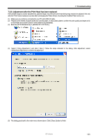
7. Troubleshooting (10) Rotate the Lever to fix the Print Head when you fix it as shown below. (11) Following the steps (18) to (20) in Color Print Head operations to remove the protection film of the Print Head, connect the Flat Cable to the Carriage PCB and cover the Carriage PCB with the Plastic Cover. Do not insert the Flat Cable at an angle. The electric current may not be stable and increase the Print Head temperature. which causes machine errors, mis-firing, and give serious damage to the Print Head. Do not repeat the insertion, or the terminal (metal) may be damaged and cause serious mis-firing. (12) Push the Stop Lever to release the lock when you close the Front Cover with both hands. (13) Turn ON the printer. (14) Keep the Maintenance Cartridge as inserted and confirm the amount of the Maintenance Solution is left more than 250 ml in the bottle. (15) Select [ Maintenance ] > [ Initial Cleaning ] from the menu and select the Print Head. (16) Load the Maintenance Solution first. Replace the Maintenance Cartridge to the well-shaken White Ink Cartridge and then load the White Ink. (17) Execute the Normal Cleaning for all the Print Heads so that the surface of the Print Head may be dried. (18) Print Nozzle Check Pattern to confirm if the replaced Print Head works OK. (See "7-2-3. Checking Print Quality with Nozzle Check Pattern"). (19) Print the Standard Check Pattern to check the alignment if the Print Head is placed properly. If the Print Heads are not aligned, then you can see the white ink printed around the color print because the white print area should be printed wider than the color area. Confirm the position of four (GT-381) or two (GT-361) White Print Heads. If not aligned, the white print should be printed wider than the original print data. (the sample is printed by CMYK ink) (20) If the quality is OK go on to the next section "7-2-8. Adjustment after the Print Head has been replaced" to complete the adjustment after the Print Head replacement. If you still see the problem in print quality, contact your Brother dealer for assistance. 122 GT-3 Series
-
 1
1 -
2
-
3
-
4
-
5
-
6
-
7
-
8
-
9
-
10
-
11
-
12
-
13
-
14
-
15
-
16
-
17
-
18
-
19
-
20
-
21
-
22
-
23
-
24
-
25
-
26
-
27
-
28
-
29
-
30
-
31
-
32
-
33
-
34
-
35
-
36
-
37
-
38
-
39
-
40
-
41
-
42
-
43
-
44
-
45
-
46
-
47
-
48
-
49
-
50
-
51
-
52
-
53
-
54
-
55
-
56
-
57
-
58
-
59
-
60
-
61
-
62
-
63
-
64
-
65
-
66
-
67
-
68
-
69
-
70
-
71
-
72
-
73
-
74
-
75
-
76
-
77
-
78
-
79
-
80
-
81
-
82
-
83
-
84
-
85
-
86
-
87
-
88
-
89
-
90
-
91
-
92
-
93
-
94
-
95
-
96
-
97
-
98
-
99
-
100
-
101
-
102
-
103
-
104
-
105
-
106
-
107
-
108
-
109
-
110
-
111
-
112
-
113
-
114
-
115
-
116
-
117
-
118
-
119
-
120
-
121
-
122
-
123
-
124
-
125
-
126
-
 127
127 -
 128
128 -
 129
129 -
 130
130 -
 131
131 -
 132
132 -
 133
133 -
 134
134 -
 135
135 -
 136
136 -
 137
137 -
138
-
139
-
140
-
141
-
142
-
143
-
144
-
145
-
146
-
147
-
148
 |
 |