Cisco 6513 Installation Guide - Page 181
Step 3, Caution, Chassis with horizontal slots
 |
View all Cisco 6513 manuals
Add to My Manuals
Save this manual to your list of manuals |
Page 181 highlights
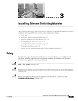
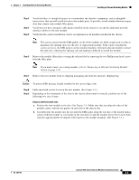
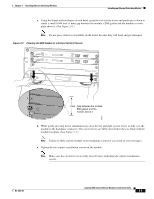
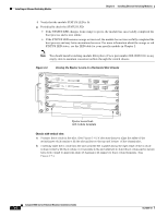
Chapter 3 Installing Ethernet Switching Modules Installing an Ethernet Switching Module Step 3 Step 4 Step 5 Verify that there is enough clearance to accommodate any interface equipment, such as pluggable transceivers, that you will install directly to the module ports. If possible, install modules between empty slots that contain only module filler plates. Verify that you have adequate cable guides installed on the chassis to accept the additional network interface cables for the new module. Verify that the captive installation screws are tightened on all modules installed in the chassis. Note This action assures that the EMI gaskets on all of the modules are fully compressed in order to maximize the opening space for the new or replacement module. If the captive installation screws are loose, the EMI gaskets on the installed modules will push adjacent modules toward the open slot, reducing the opening size and making it difficult to install the module. Step 6 Remove the module filler plate covering the selected slot by removing the two Phillips pan-head screws from the filler plate. Note If you must remove an existing module, refer to "Removing an Ethernet Switching Module" section on page 3-10. Step 7 Remove the new module from its shipping packaging and from the antistatic shipping bag. Caution To prevent ESD damage, handle modules by the carrier edges only. Step 8 Step 9 Fully open both ejector levers on the new module. (See Figure 3-1.) Depending on the orientation of the slots in the chassis (horizontal or vertical), perform one of the following two sets of steps: Chassis with horizontal slots a. Position the new module in the slot. (See Figure 3-1.) Make sure that you align the sides of the module carrier with the slot guides on each side of the chassis slot. b. Carefully slide the module into the slot until the EMI gasket along the top edge of the module makes contact with the module or cover plate in the slot above it and the module ejector levers have both closed to approximately 45 degrees with respect to the module faceplate. (See Figure 3-2.) OL-6265-03 Catalyst 6500 Series Ethernet Modules Installation Guide 3-3
-
 1
1 -
2
-
3
-
4
-
5
-
6
-
7
-
8
-
9
-
10
-
11
-
12
-
13
-
14
-
15
-
16
-
17
-
18
-
19
-
20
-
21
-
22
-
23
-
24
-
25
-
26
-
27
-
28
-
29
-
30
-
31
-
32
-
33
-
34
-
35
-
36
-
37
-
38
-
39
-
40
-
41
-
42
-
43
-
44
-
45
-
46
-
47
-
48
-
49
-
50
-
51
-
52
-
53
-
54
-
55
-
56
-
57
-
58
-
59
-
60
-
61
-
62
-
63
-
64
-
65
-
66
-
67
-
68
-
69
-
70
-
71
-
72
-
73
-
74
-
75
-
76
-
77
-
78
-
79
-
80
-
81
-
82
-
83
-
84
-
85
-
86
-
87
-
88
-
89
-
90
-
91
-
92
-
93
-
94
-
95
-
96
-
97
-
98
-
99
-
100
-
101
-
102
-
103
-
104
-
105
-
106
-
107
-
108
-
109
-
110
-
111
-
112
-
113
-
114
-
115
-
116
-
117
-
118
-
119
-
120
-
121
-
122
-
123
-
124
-
125
-
126
-
127
-
128
-
129
-
130
-
131
-
132
-
133
-
134
-
135
-
136
-
137
-
138
-
139
-
140
-
141
-
142
-
143
-
144
-
145
-
146
-
147
-
148
-
149
-
150
-
151
-
152
-
153
-
154
-
155
-
156
-
157
-
158
-
159
-
160
-
161
-
162
-
163
-
164
-
165
-
166
-
167
-
168
-
169
-
170
-
171
-
172
-
173
-
174
-
175
-
 176
176 -
 177
177 -
 178
178 -
 179
179 -
 180
180 -
 181
181 -
 182
182 -
 183
183 -
 184
184 -
 185
185 -
 186
186 -
187
-
188
-
189
-
190
-
191
-
192
-
193
-
194
-
195
-
196
-
197
-
198
-
199
-
200
-
201
-
202
-
203
-
204
-
205
-
206
-
207
-
208
-
209
-
210
-
211
-
212
-
213
-
214
-
215
-
216
-
217
-
218
-
219
-
220
-
221
-
222
-
223
-
224
-
225
-
226
-
227
-
228
-
229
-
230
-
231
-
232
-
233
-
234
-
235
-
236
-
237
-
238
-
239
-
240
-
241
-
242
-
243
-
244
-
245
-
246
-
247
-
248
-
249
-
250
-
251
-
252
-
253
-
254
 |
 |
