Cisco 6513 Installation Guide - Page 28
Table 1-5, Catalyst 6504-E Switch Features, Supports Supervisor Engine 2, Supervisor Engine 32 - models
 |
View all Cisco 6513 manuals
Add to My Manuals
Save this manual to your list of manuals |
Page 28 highlights
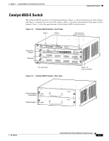
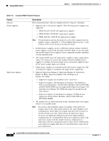
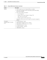
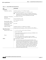
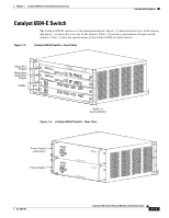
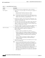
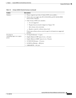
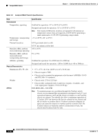
Catalyst 6504-E Switch Chapter 1 Catalyst 6500 Series Switch Chassis Overview Table 1-5 Catalyst 6504-E Switch Features Feature Chassis Power supplies Description Four horizontal slots. Slots are numbered from 1 (top) to 4 (bottom). • Supports one or two power supplies. The following power supplies are supported: - PWR-2700-AC/4 (2700 W AC-input power supply) - PWR-2700-DC/4 (2700 W DC-input power supply) Note For information and specifications for each of the supported power supplies, refer to Appendix A, "Power Supply Specifications," in the Catalyst 6500 Series Switches Installation Guide. Supervisor engines • Installed power supplies can be both AC-input, both DC-input, or one AC-input and one DC-input. Power supplies can be configured in either redundant or nonredundant mode. • All Catalyst 6500 series AC-input power supplies require single-phase source AC. Source AC can be out of phase between multiple power supplies or multiple AC-power plugs on the same power supply because all AC power supply inputs are isolated. • Single power supplies are installed in the lower power supply bay. The second power supply is installed in the upper power supply bay. • Supports Supervisor Engine 2, Supervisor Engine 32, Supervisor Engine 32 PISA, Supervisor Engine 720, and Supervisor Engine 720-10GE. - Supervisor engines are installed in slot 1 and slot 2. - Supervisor Engine 720 and Supervisor Engine 720-10GE have built-in switching fabric. Switch Fabric Modules (WS-C6500-SFM and WS-X6500-SFM2) are not supported by Supervisor Engine 720 and Supervisor Engine 720-10GE and cannot be installed in the same chassis. - Supervisor Engine 32 and Supervisor Engine 32 PISA do not support the Switch Fabric Modules ((WS-C6500-SFM and WS-X6500-SFM2). • The uplink ports are fully functional on the redundant supervisor engine when it is in standby mode. Note In systems with redundant supervisor engines, both supervisor engines must be the same model and have the same daughter card configurations. Each supervisor engine must have the resources to run the switch on its own, which means all supervisor engine resources are duplicated. Identical supervisor engine memory configurations are recommended, but are not required as long as the supervisor engine with the smaller memory configuration is sufficient to run the configured features of the switch. Additionally, each supervisor engine must have its own flash device and console port connections. 1-12 Catalyst 6500 Series Ethernet Modules Installation Guide OL-6265-03
-
 1
1 -
2
-
3
-
4
-
5
-
6
-
7
-
8
-
9
-
10
-
11
-
12
-
13
-
14
-
15
-
16
-
17
-
18
-
19
-
20
-
21
-
22
-
 23
23 -
 24
24 -
 25
25 -
 26
26 -
 27
27 -
 28
28 -
 29
29 -
 30
30 -
 31
31 -
 32
32 -
 33
33 -
34
-
35
-
36
-
37
-
38
-
39
-
40
-
41
-
42
-
43
-
44
-
45
-
46
-
47
-
48
-
49
-
50
-
51
-
52
-
53
-
54
-
55
-
56
-
57
-
58
-
59
-
60
-
61
-
62
-
63
-
64
-
65
-
66
-
67
-
68
-
69
-
70
-
71
-
72
-
73
-
74
-
75
-
76
-
77
-
78
-
79
-
80
-
81
-
82
-
83
-
84
-
85
-
86
-
87
-
88
-
89
-
90
-
91
-
92
-
93
-
94
-
95
-
96
-
97
-
98
-
99
-
100
-
101
-
102
-
103
-
104
-
105
-
106
-
107
-
108
-
109
-
110
-
111
-
112
-
113
-
114
-
115
-
116
-
117
-
118
-
119
-
120
-
121
-
122
-
123
-
124
-
125
-
126
-
127
-
128
-
129
-
130
-
131
-
132
-
133
-
134
-
135
-
136
-
137
-
138
-
139
-
140
-
141
-
142
-
143
-
144
-
145
-
146
-
147
-
148
-
149
-
150
-
151
-
152
-
153
-
154
-
155
-
156
-
157
-
158
-
159
-
160
-
161
-
162
-
163
-
164
-
165
-
166
-
167
-
168
-
169
-
170
-
171
-
172
-
173
-
174
-
175
-
176
-
177
-
178
-
179
-
180
-
181
-
182
-
183
-
184
-
185
-
186
-
187
-
188
-
189
-
190
-
191
-
192
-
193
-
194
-
195
-
196
-
197
-
198
-
199
-
200
-
201
-
202
-
203
-
204
-
205
-
206
-
207
-
208
-
209
-
210
-
211
-
212
-
213
-
214
-
215
-
216
-
217
-
218
-
219
-
220
-
221
-
222
-
223
-
224
-
225
-
226
-
227
-
228
-
229
-
230
-
231
-
232
-
233
-
234
-
235
-
236
-
237
-
238
-
239
-
240
-
241
-
242
-
243
-
244
-
245
-
246
-
247
-
248
-
249
-
250
-
251
-
252
-
253
-
254
 |
 |
