Cisco 6513 Installation Guide - Page 190
Attaching, Your ESD Grounding Strap on C-1, Caution, Warning, Step 1 - protection
 |
View all Cisco 6513 manuals
Add to My Manuals
Save this manual to your list of manuals |
Page 190 highlights
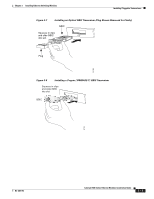
Installing Pluggable Transceivers Chapter 3 Installing Ethernet Switching Modules You will need these tools to install the GBIC transceiver: • Wrist strap or other personal grounding device to prevent ESD occurrences. • Antistatic mat or an antistatic bag to set the unpackaged GBIC transceiver on. • Fiber-optic end-face cleaning tools and inspection equipment. For information on inspecting and cleaning fiber-optic interfaces, see the document at this URL: tap://www.cisco.com/en/US/tech/tk482/tk607/technologies_white_paper09186a0080254eba.shtml Caution During this procedure, wear an ESD grounding strap to avoid ESD damage to the module. Warning Invisible laser radiation may be emitted from disconnected fibers or connectors. Do not stare into beams or view directly with optical instruments. Statement 1051 To install GBIC transceivers in a module port, perform these steps: Step 1 Attach an ESD grounding strap to your wrist and to ground. Note If you are unsure about the correct way to attach an ESD grounding strap, see the "Attaching Your ESD Grounding Strap" section on page C-1 for instructions. Step 2 Remove the GBIC transceiver from its protective packaging and verify that the GBIC transceiver is the correct type for your network. Note If this is an optical GBIC transceiver, do not remove optical bore plugs from the GBIC at this time. Step 3 Step 4 Grip the sides of the GBIC transceiver with your thumb and forefinger, carefully align the GBIC transceiver with the module's port socket opening, and carefully insert the GBIC through the socket flap and slide it into the module GBIC socket. (See Figure 3-7 for installing optical GBICs or Figure 3-8 for installing copper GBICs.) Continue sliding the GBIC transceiver into the socket until you hear a click which indicates that the GBIC is fully mated to the socket connector and that the GBIC is locked into the socket. Caution You must insert the GBIC straight into the socket (either horizontally or vertically, depending on the orientation of the socket). If you do not install the GBIC correctly or you use excessive force, you will damage the GBIC or the socket. Note GBIC transceivers have an alignment groove on each side of the transceiver to prevent incorrect insertion. (See Figure 3-9.) 3-12 Catalyst 6500 Series Ethernet Modules Installation Guide OL-6265-03
-
 1
1 -
2
-
3
-
4
-
5
-
6
-
7
-
8
-
9
-
10
-
11
-
12
-
13
-
14
-
15
-
16
-
17
-
18
-
19
-
20
-
21
-
22
-
23
-
24
-
25
-
26
-
27
-
28
-
29
-
30
-
31
-
32
-
33
-
34
-
35
-
36
-
37
-
38
-
39
-
40
-
41
-
42
-
43
-
44
-
45
-
46
-
47
-
48
-
49
-
50
-
51
-
52
-
53
-
54
-
55
-
56
-
57
-
58
-
59
-
60
-
61
-
62
-
63
-
64
-
65
-
66
-
67
-
68
-
69
-
70
-
71
-
72
-
73
-
74
-
75
-
76
-
77
-
78
-
79
-
80
-
81
-
82
-
83
-
84
-
85
-
86
-
87
-
88
-
89
-
90
-
91
-
92
-
93
-
94
-
95
-
96
-
97
-
98
-
99
-
100
-
101
-
102
-
103
-
104
-
105
-
106
-
107
-
108
-
109
-
110
-
111
-
112
-
113
-
114
-
115
-
116
-
117
-
118
-
119
-
120
-
121
-
122
-
123
-
124
-
125
-
126
-
127
-
128
-
129
-
130
-
131
-
132
-
133
-
134
-
135
-
136
-
137
-
138
-
139
-
140
-
141
-
142
-
143
-
144
-
145
-
146
-
147
-
148
-
149
-
150
-
151
-
152
-
153
-
154
-
155
-
156
-
157
-
158
-
159
-
160
-
161
-
162
-
163
-
164
-
165
-
166
-
167
-
168
-
169
-
170
-
171
-
172
-
173
-
174
-
175
-
176
-
177
-
178
-
179
-
180
-
181
-
182
-
183
-
184
-
 185
185 -
 186
186 -
 187
187 -
 188
188 -
 189
189 -
 190
190 -
 191
191 -
 192
192 -
 193
193 -
 194
194 -
 195
195 -
196
-
197
-
198
-
199
-
200
-
201
-
202
-
203
-
204
-
205
-
206
-
207
-
208
-
209
-
210
-
211
-
212
-
213
-
214
-
215
-
216
-
217
-
218
-
219
-
220
-
221
-
222
-
223
-
224
-
225
-
226
-
227
-
228
-
229
-
230
-
231
-
232
-
233
-
234
-
235
-
236
-
237
-
238
-
239
-
240
-
241
-
242
-
243
-
244
-
245
-
246
-
247
-
248
-
249
-
250
-
251
-
252
-
253
-
254
 |
 |
