Cisco 6513 Installation Guide - Page 196
Installing 10GBASE XENPAK Transceivers
 |
View all Cisco 6513 manuals
Add to My Manuals
Save this manual to your list of manuals |
Page 196 highlights
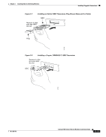
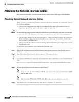
Installing Pluggable Transceivers Chapter 3 Installing Ethernet Switching Modules Installing 10GBASE XENPAK Transceivers This section provides a procedure on how to install 10GBASE XENPAK transceivers in the module. There are different types of XENPAK transceivers, but all share the same form factor. For additional information on XENPAK transceivers, including recommended cabling distances, refer to the "10-GB Transceivers" section on page B-8. You will need these tools to install the XENPAK transceiver: • Small flat-blade screwdriver to loosen or tighten the XENPAK transceiver and XENPAK port cover captive installation screws. • Wrist strap or other personal grounding device to prevent ESD occurrences. • Antistatic mat or an antistatic bag to set the XENPAK transceiver on. • Fiber-optic end-face cleaning tools and inspection equipment. For complete information on inspecting and cleaning fiber-optic connections, refer to the document at this URL: http://www.cisco.com/en/US/tech/tk482/tk607/technologies_white_paper09186a0080254eba.shtml Caution During this procedure, wear grounding wrist straps to avoid ESD damage to the module. Warning Invisible laser radiation may be emitted from disconnected fibers or connectors. Do not stare into beams or view directly with optical instruments. Statement 1051 To install a XENPAK transceiver in a 10-GBASE Ethernet module, perform these steps: Step 1 Attach an ESD grounding strap to your wrist and to ground. Note If you are unsure about the correct way to attach an ESD grounding strap, refer to the "Attaching Your ESD Grounding Strap" section on page C-1 for instructions. Step 2 Step 3 Step 4 Step 5 Step 6 Loosen and remove the two M3 Phillips pan-head screws that secure the port cover to the module faceplate and remove the port cover. Save the port cover and the two screws for future use. Remove the XENPAK transceiver from its protective packaging. If this is an optical XENPAK, do not remove optical bore plugs from the XENPAK at this time. Check the label on the XENPAK transceiver to verify that it is the correct model for your network. Align the XENPAK transceiver with the opening in the module faceplate, and slide the XENPAK transceiver into the opening until the XENPAK transceiver faceplate is in contact with the module faceplate. (See Figure 3-14.) This step ensures that the XENPAK transceiver is fully seated in the module port socket. Tighten the two captive installation screws to secure the XENPAK transceiver in the port socket. Avoid cross-threading and do not overtighten the captive installation screws. You are now ready to attach the network interface cables to the XENPAK transceiver. Note See the "Attaching the Network Interface Cables" section on page 3-22 for instructions. 3-18 Catalyst 6500 Series Ethernet Modules Installation Guide OL-6265-03
-
 1
1 -
2
-
3
-
4
-
5
-
6
-
7
-
8
-
9
-
10
-
11
-
12
-
13
-
14
-
15
-
16
-
17
-
18
-
19
-
20
-
21
-
22
-
23
-
24
-
25
-
26
-
27
-
28
-
29
-
30
-
31
-
32
-
33
-
34
-
35
-
36
-
37
-
38
-
39
-
40
-
41
-
42
-
43
-
44
-
45
-
46
-
47
-
48
-
49
-
50
-
51
-
52
-
53
-
54
-
55
-
56
-
57
-
58
-
59
-
60
-
61
-
62
-
63
-
64
-
65
-
66
-
67
-
68
-
69
-
70
-
71
-
72
-
73
-
74
-
75
-
76
-
77
-
78
-
79
-
80
-
81
-
82
-
83
-
84
-
85
-
86
-
87
-
88
-
89
-
90
-
91
-
92
-
93
-
94
-
95
-
96
-
97
-
98
-
99
-
100
-
101
-
102
-
103
-
104
-
105
-
106
-
107
-
108
-
109
-
110
-
111
-
112
-
113
-
114
-
115
-
116
-
117
-
118
-
119
-
120
-
121
-
122
-
123
-
124
-
125
-
126
-
127
-
128
-
129
-
130
-
131
-
132
-
133
-
134
-
135
-
136
-
137
-
138
-
139
-
140
-
141
-
142
-
143
-
144
-
145
-
146
-
147
-
148
-
149
-
150
-
151
-
152
-
153
-
154
-
155
-
156
-
157
-
158
-
159
-
160
-
161
-
162
-
163
-
164
-
165
-
166
-
167
-
168
-
169
-
170
-
171
-
172
-
173
-
174
-
175
-
176
-
177
-
178
-
179
-
180
-
181
-
182
-
183
-
184
-
185
-
186
-
187
-
188
-
189
-
190
-
 191
191 -
 192
192 -
 193
193 -
 194
194 -
 195
195 -
 196
196 -
 197
197 -
 198
198 -
 199
199 -
 200
200 -
 201
201 -
202
-
203
-
204
-
205
-
206
-
207
-
208
-
209
-
210
-
211
-
212
-
213
-
214
-
215
-
216
-
217
-
218
-
219
-
220
-
221
-
222
-
223
-
224
-
225
-
226
-
227
-
228
-
229
-
230
-
231
-
232
-
233
-
234
-
235
-
236
-
237
-
238
-
239
-
240
-
241
-
242
-
243
-
244
-
245
-
246
-
247
-
248
-
249
-
250
-
251
-
252
-
253
-
254
 |
 |
