Cisco 6513 Installation Guide - Page 192
Installing SFP Transceivers
 |
View all Cisco 6513 manuals
Add to My Manuals
Save this manual to your list of manuals |
Page 192 highlights
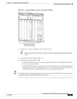
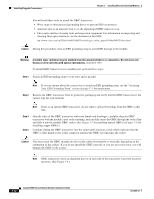
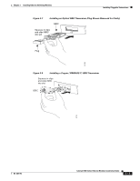
Installing Pluggable Transceivers Chapter 3 Installing Ethernet Switching Modules Figure 3-9 GBIC Transceiver Body Alignment Grooves Alignment groove 38581 Installing SFP Transceivers SFP transceivers provide an interface between an optical or copper network and the switching module. There are different types of SFP transceivers, but all share the same form factor. For additional information on SFP transceiver types, including recommended cabling distances, see Appendix B. This section provides a procedure on how to correctly install SFP transceivers in the module port socket. Caution We strongly recommend that you do not install or remove the SFP transceiver with fiber-optic cables attached to it because of the potential damage to the cables, the cable connector, or the optical interfaces in the SFP transceiver. Disconnect the network interface cable before removing or installing an SFP transceiver. SFP transceiver modules can have three types of latching devices to secure the SFP transceiver in a port socket: • Figure 3-10 shows an SFP transceiver with a Mylar tab latch. • Figure 3-11 shows an SFP transceiver with an actuator button latch. • Figure 3-12 shows an SFP transceiver that has a bale-clasp latch. Determine which type of latch your SFP transceiver uses before following the installation and removal procedures. 3-14 Catalyst 6500 Series Ethernet Modules Installation Guide OL-6265-03
-
 1
1 -
2
-
3
-
4
-
5
-
6
-
7
-
8
-
9
-
10
-
11
-
12
-
13
-
14
-
15
-
16
-
17
-
18
-
19
-
20
-
21
-
22
-
23
-
24
-
25
-
26
-
27
-
28
-
29
-
30
-
31
-
32
-
33
-
34
-
35
-
36
-
37
-
38
-
39
-
40
-
41
-
42
-
43
-
44
-
45
-
46
-
47
-
48
-
49
-
50
-
51
-
52
-
53
-
54
-
55
-
56
-
57
-
58
-
59
-
60
-
61
-
62
-
63
-
64
-
65
-
66
-
67
-
68
-
69
-
70
-
71
-
72
-
73
-
74
-
75
-
76
-
77
-
78
-
79
-
80
-
81
-
82
-
83
-
84
-
85
-
86
-
87
-
88
-
89
-
90
-
91
-
92
-
93
-
94
-
95
-
96
-
97
-
98
-
99
-
100
-
101
-
102
-
103
-
104
-
105
-
106
-
107
-
108
-
109
-
110
-
111
-
112
-
113
-
114
-
115
-
116
-
117
-
118
-
119
-
120
-
121
-
122
-
123
-
124
-
125
-
126
-
127
-
128
-
129
-
130
-
131
-
132
-
133
-
134
-
135
-
136
-
137
-
138
-
139
-
140
-
141
-
142
-
143
-
144
-
145
-
146
-
147
-
148
-
149
-
150
-
151
-
152
-
153
-
154
-
155
-
156
-
157
-
158
-
159
-
160
-
161
-
162
-
163
-
164
-
165
-
166
-
167
-
168
-
169
-
170
-
171
-
172
-
173
-
174
-
175
-
176
-
177
-
178
-
179
-
180
-
181
-
182
-
183
-
184
-
185
-
186
-
 187
187 -
 188
188 -
 189
189 -
 190
190 -
 191
191 -
 192
192 -
 193
193 -
 194
194 -
 195
195 -
 196
196 -
 197
197 -
198
-
199
-
200
-
201
-
202
-
203
-
204
-
205
-
206
-
207
-
208
-
209
-
210
-
211
-
212
-
213
-
214
-
215
-
216
-
217
-
218
-
219
-
220
-
221
-
222
-
223
-
224
-
225
-
226
-
227
-
228
-
229
-
230
-
231
-
232
-
233
-
234
-
235
-
236
-
237
-
238
-
239
-
240
-
241
-
242
-
243
-
244
-
245
-
246
-
247
-
248
-
249
-
250
-
251
-
252
-
253
-
254
 |
 |
