Cisco 6513 Installation Guide - Page 198
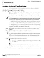
Attaching, Your ESD Grounding Strap on C-1, - 10gb module
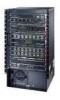 |
View all Cisco 6513 manuals
Add to My Manuals
Save this manual to your list of manuals |
Page 198 highlights
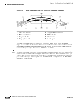
Installing Pluggable Transceivers Chapter 3 Installing Ethernet Switching Modules To install an X2 transceiver in a module port, perform these steps: Step 1 Attach an ESD grounding strap to your wrist and to ground. Note If you are unsure about the correct way to attach an ESD grounding strap, refer to the "Attaching Your ESD Grounding Strap" section on page C-1 for instructions. Step 2 Use a small flat-blade screwdriver to pry the port cover that seals the transceiver socket opening in the module faceplate and remove the port cover. Save the port cover for future use. Note Use the two arrows on the port cover as guides for inserting the screwdriver blade. Step 3 Remove the X2 transceiver from its protective packaging and check the label on the X2 transceiver body to verify that it is the correct model for your network. Note The WS-X6708-10G and the WS-X6716-10G Ethernet modules have caveats associated with the use of certain types of X2 transceivers. Refer to the module descriptions in Chapter 2 for details. See Figure 3-15 for the location of the part number label on the X2 transceiver body. Figure 3-15 X2 Transceiver Part Number Label ClLasNCs#1O50LMa0s7e/r2001 V01 X2-1100-GX2B1X-XCXMXFXaR-dXSe1NX0I:4nL0C.L1OL0UYXNYXTWXRWXYSXSXSXSXXX Cisco part number X2-10GB-XX 10-XXXX-XX 21 CFR 1040.10 Made In COUNTRY SN: LLLYYWWSSSS COM Class 1 Laser LN#50 07/2001 V01 XXXXXXXXXX 159466 Note If this is an optical X2 transceiver, do not remove optical bore plugs at this time. 3-20 Catalyst 6500 Series Ethernet Modules Installation Guide OL-6265-03
-
 1
1 -
2
-
3
-
4
-
5
-
6
-
7
-
8
-
9
-
10
-
11
-
12
-
13
-
14
-
15
-
16
-
17
-
18
-
19
-
20
-
21
-
22
-
23
-
24
-
25
-
26
-
27
-
28
-
29
-
30
-
31
-
32
-
33
-
34
-
35
-
36
-
37
-
38
-
39
-
40
-
41
-
42
-
43
-
44
-
45
-
46
-
47
-
48
-
49
-
50
-
51
-
52
-
53
-
54
-
55
-
56
-
57
-
58
-
59
-
60
-
61
-
62
-
63
-
64
-
65
-
66
-
67
-
68
-
69
-
70
-
71
-
72
-
73
-
74
-
75
-
76
-
77
-
78
-
79
-
80
-
81
-
82
-
83
-
84
-
85
-
86
-
87
-
88
-
89
-
90
-
91
-
92
-
93
-
94
-
95
-
96
-
97
-
98
-
99
-
100
-
101
-
102
-
103
-
104
-
105
-
106
-
107
-
108
-
109
-
110
-
111
-
112
-
113
-
114
-
115
-
116
-
117
-
118
-
119
-
120
-
121
-
122
-
123
-
124
-
125
-
126
-
127
-
128
-
129
-
130
-
131
-
132
-
133
-
134
-
135
-
136
-
137
-
138
-
139
-
140
-
141
-
142
-
143
-
144
-
145
-
146
-
147
-
148
-
149
-
150
-
151
-
152
-
153
-
154
-
155
-
156
-
157
-
158
-
159
-
160
-
161
-
162
-
163
-
164
-
165
-
166
-
167
-
168
-
169
-
170
-
171
-
172
-
173
-
174
-
175
-
176
-
177
-
178
-
179
-
180
-
181
-
182
-
183
-
184
-
185
-
186
-
187
-
188
-
189
-
190
-
191
-
192
-
 193
193 -
 194
194 -
 195
195 -
 196
196 -
 197
197 -
 198
198 -
 199
199 -
 200
200 -
 201
201 -
 202
202 -
 203
203 -
204
-
205
-
206
-
207
-
208
-
209
-
210
-
211
-
212
-
213
-
214
-
215
-
216
-
217
-
218
-
219
-
220
-
221
-
222
-
223
-
224
-
225
-
226
-
227
-
228
-
229
-
230
-
231
-
232
-
233
-
234
-
235
-
236
-
237
-
238
-
239
-
240
-
241
-
242
-
243
-
244
-
245
-
246
-
247
-
248
-
249
-
250
-
251
-
252
-
253
-
254
 |
 |
