Cisco 6513 Installation Guide - Page 26
Specification, Table 1-4, Catalyst 6503-E Switch Specifications - ru
 |
View all Cisco 6513 manuals
Add to My Manuals
Save this manual to your list of manuals |
Page 26 highlights
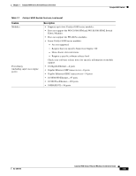
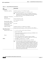
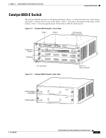
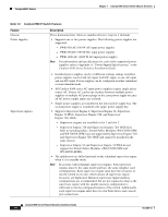
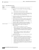
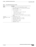
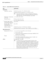
Catalyst 6503-E Switch Chapter 1 Catalyst 6500 Series Switch Chassis Overview Table 1-4 Catalyst 6503-E Switch Specifications Item Environmental Temperature, operating Temperature, nonoperating and storage Thermal transition Humidity (RH), ambient (noncondensing) operating Humidity (RH), ambient (noncondensing) nonoperating and storage Altitude, operating Physical Characteristics Dimensions (H x W x D) Weight Airflow Specification Certified for operation: 32° to 104°F (0° to 40°C) Designed and tested for operation: 32° to 130°F (0° to 55°C) Note The Catalyst 6500 series switches are equipped with internal air temperature sensors that are triggered at 104°F (40°C) generating a minor alarm and at 131°F (55°C) generating a major alarm. -4° to 149°F (-20° to 65°C) 0.5°C per minute (hot to cold) 0.33°C per minute (cold to hot) 10% to 85% 5% to 95% Certified for operation: 0 to 6500 feet (0 to 2000 m) Designed and tested for operation: -200 to 10,000 feet (-60 to 3000 m) • 7 x 17.37 x 21.75 in. (17.78 x 44.12 x 55.25 cm). • Chassis requires 4 RU. • Chassis can be mounted in equipment racks that meet ANSI/EIA 310-D and ETS 300-119 standards. • Chassis only: 33 lb (15 kg). • Chassis fully configured with 1 supervisor engine, 2 modules, 2 AC-input PEMs, and 2 AC-input power supplies: 85.4 lb (38.7 kg). WS-C6503-E-FAN-282 CFM Note To maintain proper air circulation through the Catalyst switch chassis, we recommend that you maintain a minimum 15 cm (6-inch) separation between a wall and the chassis air intake or a wall and the chassis air exhaust. You should also allow a minimum separation of 12 inches (30.5 cm) between the hot air exhaust on one chassis and the air intake on another chassis. Failure to maintain adequate air space can cause the chassis to overheat and the system to fail. On Catalyst chassis in which the airflow is from front to back, the chassis may be placed side-by-side. 1-10 Catalyst 6500 Series Ethernet Modules Installation Guide OL-6265-03
-
 1
1 -
2
-
3
-
4
-
5
-
6
-
7
-
8
-
9
-
10
-
11
-
12
-
13
-
14
-
15
-
16
-
17
-
18
-
19
-
20
-
 21
21 -
 22
22 -
 23
23 -
 24
24 -
 25
25 -
 26
26 -
 27
27 -
 28
28 -
 29
29 -
 30
30 -
 31
31 -
32
-
33
-
34
-
35
-
36
-
37
-
38
-
39
-
40
-
41
-
42
-
43
-
44
-
45
-
46
-
47
-
48
-
49
-
50
-
51
-
52
-
53
-
54
-
55
-
56
-
57
-
58
-
59
-
60
-
61
-
62
-
63
-
64
-
65
-
66
-
67
-
68
-
69
-
70
-
71
-
72
-
73
-
74
-
75
-
76
-
77
-
78
-
79
-
80
-
81
-
82
-
83
-
84
-
85
-
86
-
87
-
88
-
89
-
90
-
91
-
92
-
93
-
94
-
95
-
96
-
97
-
98
-
99
-
100
-
101
-
102
-
103
-
104
-
105
-
106
-
107
-
108
-
109
-
110
-
111
-
112
-
113
-
114
-
115
-
116
-
117
-
118
-
119
-
120
-
121
-
122
-
123
-
124
-
125
-
126
-
127
-
128
-
129
-
130
-
131
-
132
-
133
-
134
-
135
-
136
-
137
-
138
-
139
-
140
-
141
-
142
-
143
-
144
-
145
-
146
-
147
-
148
-
149
-
150
-
151
-
152
-
153
-
154
-
155
-
156
-
157
-
158
-
159
-
160
-
161
-
162
-
163
-
164
-
165
-
166
-
167
-
168
-
169
-
170
-
171
-
172
-
173
-
174
-
175
-
176
-
177
-
178
-
179
-
180
-
181
-
182
-
183
-
184
-
185
-
186
-
187
-
188
-
189
-
190
-
191
-
192
-
193
-
194
-
195
-
196
-
197
-
198
-
199
-
200
-
201
-
202
-
203
-
204
-
205
-
206
-
207
-
208
-
209
-
210
-
211
-
212
-
213
-
214
-
215
-
216
-
217
-
218
-
219
-
220
-
221
-
222
-
223
-
224
-
225
-
226
-
227
-
228
-
229
-
230
-
231
-
232
-
233
-
234
-
235
-
236
-
237
-
238
-
239
-
240
-
241
-
242
-
243
-
244
-
245
-
246
-
247
-
248
-
249
-
250
-
251
-
252
-
253
-
254
 |
 |