Cisco 6513 Installation Guide - Page 188
Removing an Ethernet Switching Module
 |
View all Cisco 6513 manuals
Add to My Manuals
Save this manual to your list of manuals |
Page 188 highlights
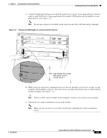
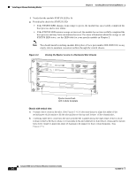
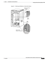
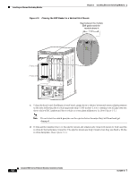
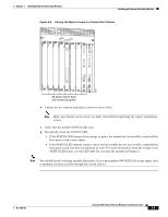
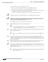
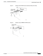
Removing an Ethernet Switching Module Chapter 3 Installing Ethernet Switching Modules Removing an Ethernet Switching Module This section describes how to remove an Ethernet switching module from the Catalyst 6500 series switch chassis. Caution During this procedure, wear grounding wrist straps to avoid ESD damage to the module. Warning Invisible laser radiation may be emitted from disconnected fibers or connectors. Do not stare into beams or view directly with optical instruments. Statement 1051 To remove a module from the chassis, perform these steps: Step 1 Attach an ESD grounding strap to your wrist and to ground. Note If you are unsure about the correct way to attach an ESD grounding strap, see the "Attaching Your ESD Grounding Strap" section on page C-1 for instructions. Step 2 Disconnect any network interface cables attached to the module. Step 3 Verify that the captive installation screws on all of the modules in the chassis are tight. Note This step ensures that the space created by the removed module is maintained. If the captive installation screws are loose, the EMI gaskets on the installed modules will push the modules toward the open slot, reducing the opening size and making it difficult to remove the module. Step 4 Step 5 Loosen the two captive screws on the module. Make sure that the two captive screws are completely unscrewed from the chassis. Depending on the orientation of the slots in the chassis (horizontal or vertical), perform one of the following two sets of steps: Horizontal slots a. Place your thumbs on the left and right ejector levers and simultaneously rotate the levers outward to unseat the module from the backplane connector. b. Grasp the front edge of the module and slide the module part of the way out of the slot. Place your other hand under the module to support the weight of the module. Do not touch the module circuitry. Vertical slots a. Place your thumbs on the ejector levers located at the top and bottom of the module, and simultaneously rotate the levers outward to unseat the module from the backplane connector. b. Grasp the edges of the module, and slide the module straight out of the slot. Do not touch the module circuitry. 3-10 Catalyst 6500 Series Ethernet Modules Installation Guide OL-6265-03
-
 1
1 -
2
-
3
-
4
-
5
-
6
-
7
-
8
-
9
-
10
-
11
-
12
-
13
-
14
-
15
-
16
-
17
-
18
-
19
-
20
-
21
-
22
-
23
-
24
-
25
-
26
-
27
-
28
-
29
-
30
-
31
-
32
-
33
-
34
-
35
-
36
-
37
-
38
-
39
-
40
-
41
-
42
-
43
-
44
-
45
-
46
-
47
-
48
-
49
-
50
-
51
-
52
-
53
-
54
-
55
-
56
-
57
-
58
-
59
-
60
-
61
-
62
-
63
-
64
-
65
-
66
-
67
-
68
-
69
-
70
-
71
-
72
-
73
-
74
-
75
-
76
-
77
-
78
-
79
-
80
-
81
-
82
-
83
-
84
-
85
-
86
-
87
-
88
-
89
-
90
-
91
-
92
-
93
-
94
-
95
-
96
-
97
-
98
-
99
-
100
-
101
-
102
-
103
-
104
-
105
-
106
-
107
-
108
-
109
-
110
-
111
-
112
-
113
-
114
-
115
-
116
-
117
-
118
-
119
-
120
-
121
-
122
-
123
-
124
-
125
-
126
-
127
-
128
-
129
-
130
-
131
-
132
-
133
-
134
-
135
-
136
-
137
-
138
-
139
-
140
-
141
-
142
-
143
-
144
-
145
-
146
-
147
-
148
-
149
-
150
-
151
-
152
-
153
-
154
-
155
-
156
-
157
-
158
-
159
-
160
-
161
-
162
-
163
-
164
-
165
-
166
-
167
-
168
-
169
-
170
-
171
-
172
-
173
-
174
-
175
-
176
-
177
-
178
-
179
-
180
-
181
-
182
-
 183
183 -
 184
184 -
 185
185 -
 186
186 -
 187
187 -
 188
188 -
 189
189 -
 190
190 -
 191
191 -
 192
192 -
 193
193 -
194
-
195
-
196
-
197
-
198
-
199
-
200
-
201
-
202
-
203
-
204
-
205
-
206
-
207
-
208
-
209
-
210
-
211
-
212
-
213
-
214
-
215
-
216
-
217
-
218
-
219
-
220
-
221
-
222
-
223
-
224
-
225
-
226
-
227
-
228
-
229
-
230
-
231
-
232
-
233
-
234
-
235
-
236
-
237
-
238
-
239
-
240
-
241
-
242
-
243
-
244
-
245
-
246
-
247
-
248
-
249
-
250
-
251
-
252
-
253
-
254
 |
 |
