Cisco 6513 Installation Guide - Page 183
Clearing the EMI Gasket in a Horizontal Slot Chassis
 |
View all Cisco 6513 manuals
Add to My Manuals
Save this manual to your list of manuals |
Page 183 highlights
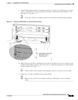
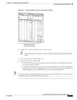
Chapter 3 Installing Ethernet Switching Modules Installing an Ethernet Switching Module c. Using the thumb and forefinger of each hand, grasp the two ejector levers and gently press down to create a small 0.040 inch (1 mm) gap between the module's EMI gasket and the module or cover plate above it. (See Figure 3-2.) Note Do not press down too forcefully on the levers because they will bend and get damaged. Figure 3-2 Clearing the EMI Gasket in a Horizontal Slot Chassis WS-X6K-SUP2-2GE 1 STATUS SYSTEMCONSOLPEWR MGRMETSET CONSOLE PORT SUPERVISOR2 CONSOLE MODE WS-X6K-SUP2-2GE 2 STATUS SYSTEMCONSOLPEWR MGRMETSET CONSOLE PORT SUPERVISOR2 CONSOLE MODE 3 Press down 4 FAN WS-X6224 STATUS 5 24 PORT 100FX 6 STATUS ACTIVE PCMCIA EJECT PCMCIA EJECT Switch Load 100% 1% Switch Load 100% 1% PORT 1 LINK PORT 1 LINK PORT 2 LINK PORT 2 LINK Press down SELECT NEXT 3 4 4 WS-C6500-SFM 55 STATUS ACTIVE SWITCH FABIRD MDL 66 1 mm Gap between the module EMI gasket and the module above it 58570 d. While gently pressing down, simultaneously close the left and right ejector levers to fully seat the module in the backplane connector. The ejector levers are fully closed when they are flush with the module faceplate. (See Figure 3-3.) Note Failure to fully seat the module in the backplane connector can result in error messages. e. Tighten the two captive installation screws on the module. Note Make sure the ejector levers are fully closed before tightening the captive installation screws. OL-6265-03 Catalyst 6500 Series Ethernet Modules Installation Guide 3-5
-
 1
1 -
2
-
3
-
4
-
5
-
6
-
7
-
8
-
9
-
10
-
11
-
12
-
13
-
14
-
15
-
16
-
17
-
18
-
19
-
20
-
21
-
22
-
23
-
24
-
25
-
26
-
27
-
28
-
29
-
30
-
31
-
32
-
33
-
34
-
35
-
36
-
37
-
38
-
39
-
40
-
41
-
42
-
43
-
44
-
45
-
46
-
47
-
48
-
49
-
50
-
51
-
52
-
53
-
54
-
55
-
56
-
57
-
58
-
59
-
60
-
61
-
62
-
63
-
64
-
65
-
66
-
67
-
68
-
69
-
70
-
71
-
72
-
73
-
74
-
75
-
76
-
77
-
78
-
79
-
80
-
81
-
82
-
83
-
84
-
85
-
86
-
87
-
88
-
89
-
90
-
91
-
92
-
93
-
94
-
95
-
96
-
97
-
98
-
99
-
100
-
101
-
102
-
103
-
104
-
105
-
106
-
107
-
108
-
109
-
110
-
111
-
112
-
113
-
114
-
115
-
116
-
117
-
118
-
119
-
120
-
121
-
122
-
123
-
124
-
125
-
126
-
127
-
128
-
129
-
130
-
131
-
132
-
133
-
134
-
135
-
136
-
137
-
138
-
139
-
140
-
141
-
142
-
143
-
144
-
145
-
146
-
147
-
148
-
149
-
150
-
151
-
152
-
153
-
154
-
155
-
156
-
157
-
158
-
159
-
160
-
161
-
162
-
163
-
164
-
165
-
166
-
167
-
168
-
169
-
170
-
171
-
172
-
173
-
174
-
175
-
176
-
177
-
 178
178 -
 179
179 -
 180
180 -
 181
181 -
 182
182 -
 183
183 -
 184
184 -
 185
185 -
 186
186 -
 187
187 -
 188
188 -
189
-
190
-
191
-
192
-
193
-
194
-
195
-
196
-
197
-
198
-
199
-
200
-
201
-
202
-
203
-
204
-
205
-
206
-
207
-
208
-
209
-
210
-
211
-
212
-
213
-
214
-
215
-
216
-
217
-
218
-
219
-
220
-
221
-
222
-
223
-
224
-
225
-
226
-
227
-
228
-
229
-
230
-
231
-
232
-
233
-
234
-
235
-
236
-
237
-
238
-
239
-
240
-
241
-
242
-
243
-
244
-
245
-
246
-
247
-
248
-
249
-
250
-
251
-
252
-
253
-
254
 |
 |
