Cisco 6513 Installation Guide - Page 194
Attaching, Your ESD Grounding Strap on C-1, Caution, Step 1
 |
View all Cisco 6513 manuals
Add to My Manuals
Save this manual to your list of manuals |
Page 194 highlights
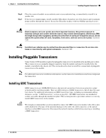
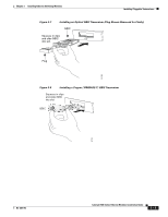
Installing Pluggable Transceivers Chapter 3 Installing Ethernet Switching Modules Note Removing and installing an SFP transceiver can shorten its useful life. Do not remove and insert SFP transceivers more often than is absolutely necessary. Caution The SFP transceivers are static-sensitive devices. Always use an ESD wrist strap or similar individual grounding device when handling SFP transceivers or coming in contact with modules. To install an SFP transceiver, perform these steps: Step 1 Attach an ESD grounding strap to your wrist and to ground. Note If you are unsure about the correct way to attach an ESD grounding strap, see the "Attaching Your ESD Grounding Strap" section on page C-1 for instructions. Step 2 Remove the SFP transceiver from its protective packaging and check the label on the SFP transceiver body to verify that you have the correct model for your network. Find the send (TX) and receive (RX) markings that identify the top side of the SFP transceiver and position the SFP transceiver in front of the socket opening. Note For optical SFP transceivers, do not remove the optical bore dust plugs until directed to do so. Note On some SFP transceivers, the TX and RX marking might be replaced by arrowheads pointing from the SFP transceiver connector (transmit direction or TX) and toward the connector (receive direction or RX). Note Different Cisco modules have different SFP module socket configurations. Your module could have either a latch-up or a latch-down orientation. Ensure that you are installing the SFP transceiver in the correct orientation for your Cisco device. 3-16 Catalyst 6500 Series Ethernet Modules Installation Guide OL-6265-03
-
 1
1 -
2
-
3
-
4
-
5
-
6
-
7
-
8
-
9
-
10
-
11
-
12
-
13
-
14
-
15
-
16
-
17
-
18
-
19
-
20
-
21
-
22
-
23
-
24
-
25
-
26
-
27
-
28
-
29
-
30
-
31
-
32
-
33
-
34
-
35
-
36
-
37
-
38
-
39
-
40
-
41
-
42
-
43
-
44
-
45
-
46
-
47
-
48
-
49
-
50
-
51
-
52
-
53
-
54
-
55
-
56
-
57
-
58
-
59
-
60
-
61
-
62
-
63
-
64
-
65
-
66
-
67
-
68
-
69
-
70
-
71
-
72
-
73
-
74
-
75
-
76
-
77
-
78
-
79
-
80
-
81
-
82
-
83
-
84
-
85
-
86
-
87
-
88
-
89
-
90
-
91
-
92
-
93
-
94
-
95
-
96
-
97
-
98
-
99
-
100
-
101
-
102
-
103
-
104
-
105
-
106
-
107
-
108
-
109
-
110
-
111
-
112
-
113
-
114
-
115
-
116
-
117
-
118
-
119
-
120
-
121
-
122
-
123
-
124
-
125
-
126
-
127
-
128
-
129
-
130
-
131
-
132
-
133
-
134
-
135
-
136
-
137
-
138
-
139
-
140
-
141
-
142
-
143
-
144
-
145
-
146
-
147
-
148
-
149
-
150
-
151
-
152
-
153
-
154
-
155
-
156
-
157
-
158
-
159
-
160
-
161
-
162
-
163
-
164
-
165
-
166
-
167
-
168
-
169
-
170
-
171
-
172
-
173
-
174
-
175
-
176
-
177
-
178
-
179
-
180
-
181
-
182
-
183
-
184
-
185
-
186
-
187
-
188
-
 189
189 -
 190
190 -
 191
191 -
 192
192 -
 193
193 -
 194
194 -
 195
195 -
 196
196 -
 197
197 -
 198
198 -
 199
199 -
200
-
201
-
202
-
203
-
204
-
205
-
206
-
207
-
208
-
209
-
210
-
211
-
212
-
213
-
214
-
215
-
216
-
217
-
218
-
219
-
220
-
221
-
222
-
223
-
224
-
225
-
226
-
227
-
228
-
229
-
230
-
231
-
232
-
233
-
234
-
235
-
236
-
237
-
238
-
239
-
240
-
241
-
242
-
243
-
244
-
245
-
246
-
247
-
248
-
249
-
250
-
251
-
252
-
253
-
254
 |
 |
