Cisco 6513 Installation Guide - Page 200
Attaching the Network Interface Cables
 |
View all Cisco 6513 manuals
Add to My Manuals
Save this manual to your list of manuals |
Page 200 highlights
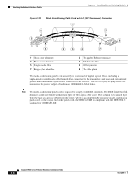
Attaching the Network Interface Cables Chapter 3 Installing Ethernet Switching Modules Attaching the Network Interface Cables This section describes how to attach network interface cables (optical and copper) to the modules. Attaching Optical Network Interface Cables Before you remove the dust plugs from the connector optical bores and make any connections, observe the following guidelines: • Always keep the protective dust plugs on the unplugged fiber-optic cable connectors and the transceiver optical bores until you are ready to make a connection. Caution Do not remove the plugs from the transceiver optical bores or the fiber-optic cable until you are ready to connect the cable. The plugs protect the transceiver optical bores and cable from contamination. • Always inspect and clean the SC or the LC connector end-faces just before making any connections. Refer to the Tip on inspecting and cleaning fiber-optic connections for a pointer to a fiber-optic inspection and cleaning document. • Always grasp the SC or the LC connector housing rather than the fiber-optic cable to plug or unplug the fiber-optic cable. To install the optical interface cables, perform the following steps: Step 1 Step 2 Remove the dust plugs from the network interface cable optical connectors. Save the dust plugs for future use. Immediately inspect and clean the optical connector's fiber-optic end-faces. Tip For complete information on inspecting and cleaning fiber-optic connections, see the document at this URL: http://www.cisco.com/en/US/tech/tk482/tk607/technologies_white_paper09186a0080254eba.shtml Step 3 Remove the dust plugs from the transceiver optical bores. Note If you are using the LX/LH GBIC with MMF, you need to install a patch cord between the GBIC and the MMF cable. Note The Read-Only WDM GBIC (WDM-GBIC-REC=) has only one optical bore (receive). Step 4 Immediately attach the network interface cable optical connector to the transceiver. 3-22 Catalyst 6500 Series Ethernet Modules Installation Guide OL-6265-03
-
 1
1 -
2
-
3
-
4
-
5
-
6
-
7
-
8
-
9
-
10
-
11
-
12
-
13
-
14
-
15
-
16
-
17
-
18
-
19
-
20
-
21
-
22
-
23
-
24
-
25
-
26
-
27
-
28
-
29
-
30
-
31
-
32
-
33
-
34
-
35
-
36
-
37
-
38
-
39
-
40
-
41
-
42
-
43
-
44
-
45
-
46
-
47
-
48
-
49
-
50
-
51
-
52
-
53
-
54
-
55
-
56
-
57
-
58
-
59
-
60
-
61
-
62
-
63
-
64
-
65
-
66
-
67
-
68
-
69
-
70
-
71
-
72
-
73
-
74
-
75
-
76
-
77
-
78
-
79
-
80
-
81
-
82
-
83
-
84
-
85
-
86
-
87
-
88
-
89
-
90
-
91
-
92
-
93
-
94
-
95
-
96
-
97
-
98
-
99
-
100
-
101
-
102
-
103
-
104
-
105
-
106
-
107
-
108
-
109
-
110
-
111
-
112
-
113
-
114
-
115
-
116
-
117
-
118
-
119
-
120
-
121
-
122
-
123
-
124
-
125
-
126
-
127
-
128
-
129
-
130
-
131
-
132
-
133
-
134
-
135
-
136
-
137
-
138
-
139
-
140
-
141
-
142
-
143
-
144
-
145
-
146
-
147
-
148
-
149
-
150
-
151
-
152
-
153
-
154
-
155
-
156
-
157
-
158
-
159
-
160
-
161
-
162
-
163
-
164
-
165
-
166
-
167
-
168
-
169
-
170
-
171
-
172
-
173
-
174
-
175
-
176
-
177
-
178
-
179
-
180
-
181
-
182
-
183
-
184
-
185
-
186
-
187
-
188
-
189
-
190
-
191
-
192
-
193
-
194
-
 195
195 -
 196
196 -
 197
197 -
 198
198 -
 199
199 -
 200
200 -
 201
201 -
 202
202 -
 203
203 -
 204
204 -
 205
205 -
206
-
207
-
208
-
209
-
210
-
211
-
212
-
213
-
214
-
215
-
216
-
217
-
218
-
219
-
220
-
221
-
222
-
223
-
224
-
225
-
226
-
227
-
228
-
229
-
230
-
231
-
232
-
233
-
234
-
235
-
236
-
237
-
238
-
239
-
240
-
241
-
242
-
243
-
244
-
245
-
246
-
247
-
248
-
249
-
250
-
251
-
252
-
253
-
254
 |
 |
