Cisco 6513 Installation Guide - Page 187
Closing the Ejector Levers in a Vertical Slot Chassis
 |
View all Cisco 6513 manuals
Add to My Manuals
Save this manual to your list of manuals |
Page 187 highlights
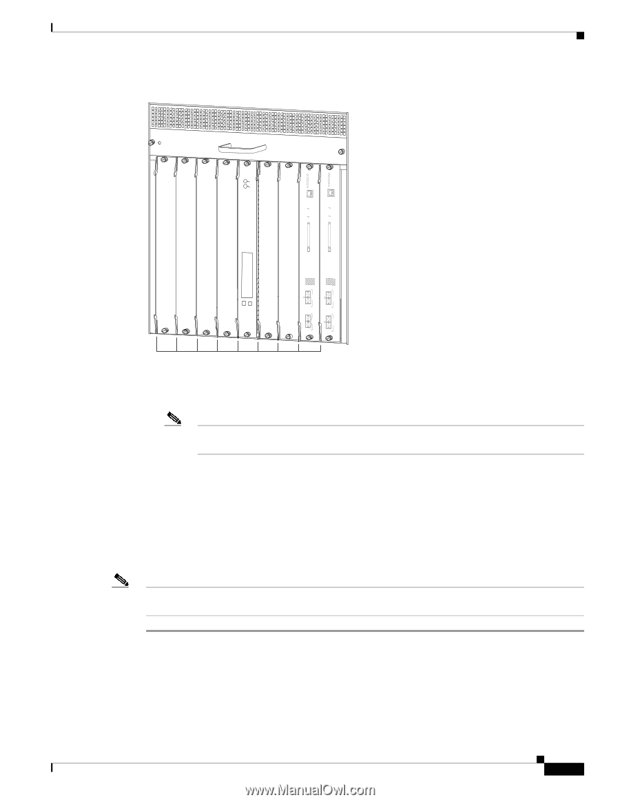
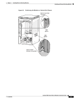
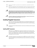
Chapter 3 Installing Ethernet Switching Modules Installing an Ethernet Switching Module Figure 3-6 Closing the Ejector Levers in a Vertical Slot Chassis FAN STATUS WS-X6K-SUP2-2GE STATUSSYSTEMCONSOLPEWR MGRMETSET CONSOLE SUPERVISOR2 WS-X6K-SUP2-2GE STATUSSYSTEMCONSOLPEWR MGRMETSET CONSOLE SUPERVISOR2 WS-X6224 24 PORT 100FX STATUS ACTIVE CONSOLE PORT MODE CONSOLE PORT MODE PCMCIA PCMCIA EJECT EJECT Switch Load 100% 1% Switch Load 100% 1% PORT 1 PORT 1 SELECT NEXT PORT 2 PORT 2 63587 All ejector levers flush with module faceplate e. Tighten the tw o captive installation screw son the m odule. Note Make sure that the ejector levers are fully closed before tightening the captive installation screws. f. Verify that the module STATUS LED is lit. g. Periodically check the STATUS LED: • If the STATUS LED changes from orange to green, the module has successfully completed the boot process and is now online. • If the STATUS LED remains orange or turns red, the module has not successfully completed the boot process and may have encountered an error. For more information about the orange or red STATUS LED states, see the LED table for your specific module in Chapter 2. Note You should install switching-module filler plates (Cisco part number 800-00292-01) in any empty slots to maintain consistent airflow through the switch chassis. OL-6265-03 Catalyst 6500 Series Ethernet Modules Installation Guide 3-9
-
 1
1 -
2
-
3
-
4
-
5
-
6
-
7
-
8
-
9
-
10
-
11
-
12
-
13
-
14
-
15
-
16
-
17
-
18
-
19
-
20
-
21
-
22
-
23
-
24
-
25
-
26
-
27
-
28
-
29
-
30
-
31
-
32
-
33
-
34
-
35
-
36
-
37
-
38
-
39
-
40
-
41
-
42
-
43
-
44
-
45
-
46
-
47
-
48
-
49
-
50
-
51
-
52
-
53
-
54
-
55
-
56
-
57
-
58
-
59
-
60
-
61
-
62
-
63
-
64
-
65
-
66
-
67
-
68
-
69
-
70
-
71
-
72
-
73
-
74
-
75
-
76
-
77
-
78
-
79
-
80
-
81
-
82
-
83
-
84
-
85
-
86
-
87
-
88
-
89
-
90
-
91
-
92
-
93
-
94
-
95
-
96
-
97
-
98
-
99
-
100
-
101
-
102
-
103
-
104
-
105
-
106
-
107
-
108
-
109
-
110
-
111
-
112
-
113
-
114
-
115
-
116
-
117
-
118
-
119
-
120
-
121
-
122
-
123
-
124
-
125
-
126
-
127
-
128
-
129
-
130
-
131
-
132
-
133
-
134
-
135
-
136
-
137
-
138
-
139
-
140
-
141
-
142
-
143
-
144
-
145
-
146
-
147
-
148
-
149
-
150
-
151
-
152
-
153
-
154
-
155
-
156
-
157
-
158
-
159
-
160
-
161
-
162
-
163
-
164
-
165
-
166
-
167
-
168
-
169
-
170
-
171
-
172
-
173
-
174
-
175
-
176
-
177
-
178
-
179
-
180
-
181
-
 182
182 -
 183
183 -
 184
184 -
 185
185 -
 186
186 -
 187
187 -
 188
188 -
 189
189 -
 190
190 -
 191
191 -
 192
192 -
193
-
194
-
195
-
196
-
197
-
198
-
199
-
200
-
201
-
202
-
203
-
204
-
205
-
206
-
207
-
208
-
209
-
210
-
211
-
212
-
213
-
214
-
215
-
216
-
217
-
218
-
219
-
220
-
221
-
222
-
223
-
224
-
225
-
226
-
227
-
228
-
229
-
230
-
231
-
232
-
233
-
234
-
235
-
236
-
237
-
238
-
239
-
240
-
241
-
242
-
243
-
244
-
245
-
246
-
247
-
248
-
249
-
250
-
251
-
252
-
253
-
254
 |
 |