Cisco 6513 Installation Guide - Page 189
Installing Pluggable Transceivers
 |
View all Cisco 6513 manuals
Add to My Manuals
Save this manual to your list of manuals |
Page 189 highlights
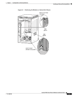
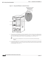
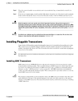
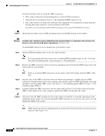
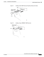
Chapter 3 Installing Ethernet Switching Modules Installing Pluggable Transceivers Step 6 Step 7 Place the removed module on an antistatic mat or in an antistatic bag, or immediately reinstall it in another slot. If the slot is to remain empty, install a module filler plate to keep dust out of the chassis and to maintain proper airflow through the chassis. Secure the filler plate in place with two Phillips pan-head screws. Warning Blank faceplates and cover panels serve three important functions: they prevent exposure to hazardous voltages and currents inside the chassis; they contain electromagnetic interference (EMI) that might disrupt other equipment; and they direct the flow of cooling air through the chassis. Do not operate the system unless all cards, faceplates, front covers, and rear covers are in place. Statement 1029 Warning Invisible laser radiation may be emitted from disconnected fibers or connectors. Do not stare into beams or view directly with optical instruments. Statement 1051 Installing Pluggable Transceivers Some Catalyst 6500 modules require that pluggable transceivers be installed in the module port sockets. These transceivers are normally shipped separately from the module and must be installed after the module is installed in the chassis slot. This section describes how to install the various kinds of pluggable transceivers in the module. Note For additional transceiver installation information, see the transceiver installation note that accompanied the transceiver. Installing GBIC Transceivers GBIC transceivers are 1000BASE-X devices that provide an interface between an optical or copper network and the switching module. There are different types of GBIC transceivers, but all share the same form factor. For additional information on GBIC transceiver types, including recommended cabling distances, see the "1-GB Transceivers" section on page B-3. All GBIC transceivers are installed in sockets accessible through the module faceplate. This section provides a procedure on how to correctly install GBIC transceivers in the module. Caution We strongly recommend that you do not install or remove the GBIC transceiver module with a fiber-optic cable attached to it because of the potential damage to the cable, the cable connector, or the optical interfaces in the GBIC transceiver. Disconnect the network interface cable before removing or installing a GBIC transceiver. OL-6265-03 Catalyst 6500 Series Ethernet Modules Installation Guide 3-11
-
 1
1 -
2
-
3
-
4
-
5
-
6
-
7
-
8
-
9
-
10
-
11
-
12
-
13
-
14
-
15
-
16
-
17
-
18
-
19
-
20
-
21
-
22
-
23
-
24
-
25
-
26
-
27
-
28
-
29
-
30
-
31
-
32
-
33
-
34
-
35
-
36
-
37
-
38
-
39
-
40
-
41
-
42
-
43
-
44
-
45
-
46
-
47
-
48
-
49
-
50
-
51
-
52
-
53
-
54
-
55
-
56
-
57
-
58
-
59
-
60
-
61
-
62
-
63
-
64
-
65
-
66
-
67
-
68
-
69
-
70
-
71
-
72
-
73
-
74
-
75
-
76
-
77
-
78
-
79
-
80
-
81
-
82
-
83
-
84
-
85
-
86
-
87
-
88
-
89
-
90
-
91
-
92
-
93
-
94
-
95
-
96
-
97
-
98
-
99
-
100
-
101
-
102
-
103
-
104
-
105
-
106
-
107
-
108
-
109
-
110
-
111
-
112
-
113
-
114
-
115
-
116
-
117
-
118
-
119
-
120
-
121
-
122
-
123
-
124
-
125
-
126
-
127
-
128
-
129
-
130
-
131
-
132
-
133
-
134
-
135
-
136
-
137
-
138
-
139
-
140
-
141
-
142
-
143
-
144
-
145
-
146
-
147
-
148
-
149
-
150
-
151
-
152
-
153
-
154
-
155
-
156
-
157
-
158
-
159
-
160
-
161
-
162
-
163
-
164
-
165
-
166
-
167
-
168
-
169
-
170
-
171
-
172
-
173
-
174
-
175
-
176
-
177
-
178
-
179
-
180
-
181
-
182
-
183
-
 184
184 -
 185
185 -
 186
186 -
 187
187 -
 188
188 -
 189
189 -
 190
190 -
 191
191 -
 192
192 -
 193
193 -
 194
194 -
195
-
196
-
197
-
198
-
199
-
200
-
201
-
202
-
203
-
204
-
205
-
206
-
207
-
208
-
209
-
210
-
211
-
212
-
213
-
214
-
215
-
216
-
217
-
218
-
219
-
220
-
221
-
222
-
223
-
224
-
225
-
226
-
227
-
228
-
229
-
230
-
231
-
232
-
233
-
234
-
235
-
236
-
237
-
238
-
239
-
240
-
241
-
242
-
243
-
244
-
245
-
246
-
247
-
248
-
249
-
250
-
251
-
252
-
253
-
254
 |
 |
