Cisco IE-3000-8TC Installation Guide - Page 105
Connecting a PC or a Terminal to the Console Port, network
 |
View all Cisco IE-3000-8TC manuals
Add to My Manuals
Save this manual to your list of manuals |
Page 105 highlights
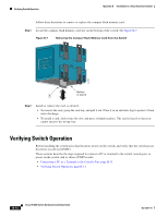
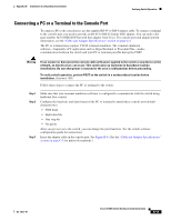
Appendix B Installation In a Hazardous Environment Verifying Switch Operation Connecting a PC or a Terminal to the Console Port To connect a PC to the console port, use the supplied RJ-45-to-DB-9 adapter cable. To connect a terminal to the console port, you need to provide an RJ-45-to-DB-25 female DTE adapter. You can order a kit (part number ACS-DSBUASYN=) with that adapter from Cisco. For console-port and adapter-pinout information, see the "Cable and Adapter Specifications" section on page C-4. The PC or terminal must support VT100 terminal emulation. The terminal-emulation software-frequently a PC application such as HyperTerminal or Procomm Plus-makes communication between the switch and your PC or terminal possible during the POST. Warning If you connect or disconnect the console cable with power applied to the switch or any device on the network, an electrical arc can occur. This could cause an explosion in hazardous location installations. Be sure that power is removed or the area is nonhazardous before proceeding. To verify switch operation, perform POST on the switch in a nonhazardous location before installation. Statement 1065 Follow these steps to connect the PC or terminal to the switch: Step 1 Step 2 Step 3 Make sure that your terminal-emulation software is configured to communicate with the switch using hardware flow control. Configure the baud rate and data format of the PC or terminal to match these console-port default characteristics: • 9600 baud • Eight data bits • One stop bit • No parity After you get access to the switch, you can change the port baud rate. See the switch software configuration guide for instructions. Insert the adapter cable in the console port. See Figure B-8. (See the "Cable and Adapter Specifications" section on page C-4 for pinout descriptions.) OL-13017-01 Cisco IE 3000 Switch Hardware Installation Guide B-15
-
 1
1 -
2
-
3
-
4
-
5
-
6
-
7
-
8
-
9
-
10
-
11
-
12
-
13
-
14
-
15
-
16
-
17
-
18
-
19
-
20
-
21
-
22
-
23
-
24
-
25
-
26
-
27
-
28
-
29
-
30
-
31
-
32
-
33
-
34
-
35
-
36
-
37
-
38
-
39
-
40
-
41
-
42
-
43
-
44
-
45
-
46
-
47
-
48
-
49
-
50
-
51
-
52
-
53
-
54
-
55
-
56
-
57
-
58
-
59
-
60
-
61
-
62
-
63
-
64
-
65
-
66
-
67
-
68
-
69
-
70
-
71
-
72
-
73
-
74
-
75
-
76
-
77
-
78
-
79
-
80
-
81
-
82
-
83
-
84
-
85
-
86
-
87
-
88
-
89
-
90
-
91
-
92
-
93
-
94
-
95
-
96
-
97
-
98
-
99
-
 100
100 -
 101
101 -
 102
102 -
 103
103 -
 104
104 -
 105
105 -
 106
106 -
 107
107 -
 108
108 -
 109
109 -
 110
110 -
111
-
112
-
113
-
114
-
115
-
116
-
117
-
118
-
119
-
120
-
121
-
122
-
123
-
124
-
125
-
126
-
127
-
128
-
129
-
130
-
131
-
132
-
133
-
134
-
135
-
136
-
137
-
138
-
139
-
140
-
141
-
142
-
143
-
144
-
145
-
146
-
147
-
148
-
149
-
150
-
151
-
152
-
153
-
154
-
155
-
156
-
157
-
158
-
159
-
160
-
161
-
162
-
163
-
164
-
165
-
166
-
167
-
168
-
169
-
170
 |
 |
