Cisco IE-3000-8TC Installation Guide - Page 46
Completed DC Power Connections on the Power and Relay Connector, External device 1
 |
View all Cisco IE-3000-8TC manuals
Add to My Manuals
Save this manual to your list of manuals |
Page 46 highlights
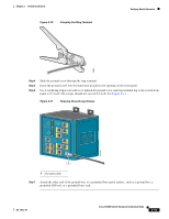
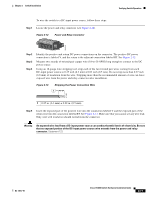
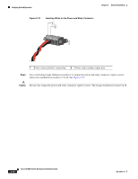
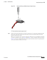
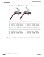
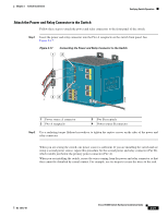
Verifying Switch Operation Chapter 2 Switch Installation Figure 2-16 Completed DC Power Connections on the Power and Relay Connector 1 2 3 4 V RT A A 5 6 7 8 V RT A A 201818 1 Power source A positive connection 2 Power source A return connection 3 External device 1, relay wire connection 4 External device 1, relay wire connection 5 Power source B positive connection 6 Power source B return connection 7 External device 2, relay wire connection 8 External device 2, relay wire connection If your power source is -48 VDC, this table descibes the your wiring connections for Figure 2-16. 1 Power source A return connection 2 Power source A -48 VDC connection 3 External device 1, relay wire connection 4 External device 1, relay wire connection 5 Power source B return connection 6 Power source B -48 VDC connection 7 External device 2, relay wire connection 8 External device 2, relay wire connection Step 8 (Optional) If you plan to connect external alarm devices to the alarm relays and the switch is already installed, go to the "Wiring the External Alarms" section on page 2-33. Otherwise, go to the "Verifying Switch Operation" section on page 2-11. 2-20 Cisco IE 3000 Switch Hardware Installation Guide OL-13017-01
-
 1
1 -
2
-
3
-
4
-
5
-
6
-
7
-
8
-
9
-
10
-
11
-
12
-
13
-
14
-
15
-
16
-
17
-
18
-
19
-
20
-
21
-
22
-
23
-
24
-
25
-
26
-
27
-
28
-
29
-
30
-
31
-
32
-
33
-
34
-
35
-
36
-
37
-
38
-
39
-
40
-
 41
41 -
 42
42 -
 43
43 -
 44
44 -
 45
45 -
 46
46 -
 47
47 -
 48
48 -
 49
49 -
 50
50 -
 51
51 -
52
-
53
-
54
-
55
-
56
-
57
-
58
-
59
-
60
-
61
-
62
-
63
-
64
-
65
-
66
-
67
-
68
-
69
-
70
-
71
-
72
-
73
-
74
-
75
-
76
-
77
-
78
-
79
-
80
-
81
-
82
-
83
-
84
-
85
-
86
-
87
-
88
-
89
-
90
-
91
-
92
-
93
-
94
-
95
-
96
-
97
-
98
-
99
-
100
-
101
-
102
-
103
-
104
-
105
-
106
-
107
-
108
-
109
-
110
-
111
-
112
-
113
-
114
-
115
-
116
-
117
-
118
-
119
-
120
-
121
-
122
-
123
-
124
-
125
-
126
-
127
-
128
-
129
-
130
-
131
-
132
-
133
-
134
-
135
-
136
-
137
-
138
-
139
-
140
-
141
-
142
-
143
-
144
-
145
-
146
-
147
-
148
-
149
-
150
-
151
-
152
-
153
-
154
-
155
-
156
-
157
-
158
-
159
-
160
-
161
-
162
-
163
-
164
-
165
-
166
-
167
-
168
-
169
-
170
 |
 |
