Cisco IE-3000-8TC Installation Guide - Page 40
Stripping the Ground Wire
 |
View all Cisco IE-3000-8TC manuals
Add to My Manuals
Save this manual to your list of manuals |
Page 40 highlights
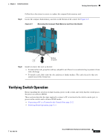
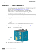
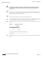
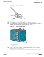
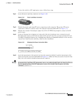
Verifying Switch Operation Chapter 2 Switch Installation Warning This equipment is intended to be grounded to comply with emission and immunity requirements. Ensure that the switch functional ground lug is connected to earth ground during normal use. Statement 1064 Caution To make sure that the equipment is reliably connected to earth ground, follow the grounding procedure instructions, and use a UL-listed ring terminal lug suitable for number 10-to-12 AWG wire, such as Thomas & Bett part number 10RCR or equivalent. Note Use at least a 4mm2 conductor to connect to the external grounding screw. Step 1 Step 2 Use a standard Phillips screwdriver or a ratcheting torque screwdriver with a Phillips head to remove the ground screw from the front panel of the switch. Store the ground screw for later use. Use a wire-stripping tool to strip the 10-gauge wire to 0.5 inch. (12.7 mm) ± 0.02 inch (0.5 mm). See Figure 2-9. Figure 2-9 Stripping the Ground Wire 1 104908 2 3 1 0.5 in. (12.7 mm) ± 0.02 in. (0.5 mm) 3 Wire lead 2 Insulation Step 3 Insert the ground wire into the ring terminal lug, and using a crimping tool, crimp the ring terminal to the wire. 2-14 Cisco IE 3000 Switch Hardware Installation Guide OL-13017-01
-
 1
1 -
2
-
3
-
4
-
5
-
6
-
7
-
8
-
9
-
10
-
11
-
12
-
13
-
14
-
15
-
16
-
17
-
18
-
19
-
20
-
21
-
22
-
23
-
24
-
25
-
26
-
27
-
28
-
29
-
30
-
31
-
32
-
33
-
34
-
 35
35 -
 36
36 -
 37
37 -
 38
38 -
 39
39 -
 40
40 -
 41
41 -
 42
42 -
 43
43 -
 44
44 -
 45
45 -
46
-
47
-
48
-
49
-
50
-
51
-
52
-
53
-
54
-
55
-
56
-
57
-
58
-
59
-
60
-
61
-
62
-
63
-
64
-
65
-
66
-
67
-
68
-
69
-
70
-
71
-
72
-
73
-
74
-
75
-
76
-
77
-
78
-
79
-
80
-
81
-
82
-
83
-
84
-
85
-
86
-
87
-
88
-
89
-
90
-
91
-
92
-
93
-
94
-
95
-
96
-
97
-
98
-
99
-
100
-
101
-
102
-
103
-
104
-
105
-
106
-
107
-
108
-
109
-
110
-
111
-
112
-
113
-
114
-
115
-
116
-
117
-
118
-
119
-
120
-
121
-
122
-
123
-
124
-
125
-
126
-
127
-
128
-
129
-
130
-
131
-
132
-
133
-
134
-
135
-
136
-
137
-
138
-
139
-
140
-
141
-
142
-
143
-
144
-
145
-
146
-
147
-
148
-
149
-
150
-
151
-
152
-
153
-
154
-
155
-
156
-
157
-
158
-
159
-
160
-
161
-
162
-
163
-
164
-
165
-
166
-
167
-
168
-
169
-
170
 |
 |
