Cisco IE-3000-8TC Installation Guide - Page 141
B-39, Pushing the Module Latches Up and Positioning the Hardware, B-40, Pushing
 |
View all Cisco IE-3000-8TC manuals
Add to My Manuals
Save this manual to your list of manuals |
Page 141 highlights
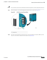
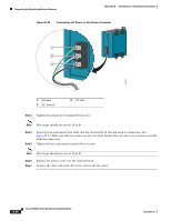
Appendix B Installation In a Hazardous Environment Connecting the Switch to the Power Converter Step 2 Push the upper modules latches (at the top of the switch and the power converter) up and the lower module latches (at the bottom of the switch and the power converter) down. See Figure B-39. Figure B-39 Pushing the Module Latches Up and Positioning the Hardware 202296 Step 3 Step 4 Put the two modules together so that the power module fits in the switch recess. Push the upper module latches down and the lower module latches up to secure the power converter to the switch. See Figure B-40. Figure B-40 Pushing the Latches In CONSOLE 202297 Pwr A (24VDC or 48 VDC) Rtn A Major Alarm 5 ! WARNING Tpeploohewwicseetrurrinccciotosrmrhddois.gchbkTteohfdoairrsveecedosumnecnroevericecthtintehtghareunisnkotitwn.oeof Pwr B (24VDC or 48 VDC) 1 Rtn B 6 Minor Alarm 2 Express Setup System Pwr A Alarm Pwr B 7 Setup 1 3 8 2 4 Cisco Catalyst OL-13017-01 Cisco IE 3000 Switch Hardware Installation Guide B-51
-
 1
1 -
2
-
3
-
4
-
5
-
6
-
7
-
8
-
9
-
10
-
11
-
12
-
13
-
14
-
15
-
16
-
17
-
18
-
19
-
20
-
21
-
22
-
23
-
24
-
25
-
26
-
27
-
28
-
29
-
30
-
31
-
32
-
33
-
34
-
35
-
36
-
37
-
38
-
39
-
40
-
41
-
42
-
43
-
44
-
45
-
46
-
47
-
48
-
49
-
50
-
51
-
52
-
53
-
54
-
55
-
56
-
57
-
58
-
59
-
60
-
61
-
62
-
63
-
64
-
65
-
66
-
67
-
68
-
69
-
70
-
71
-
72
-
73
-
74
-
75
-
76
-
77
-
78
-
79
-
80
-
81
-
82
-
83
-
84
-
85
-
86
-
87
-
88
-
89
-
90
-
91
-
92
-
93
-
94
-
95
-
96
-
97
-
98
-
99
-
100
-
101
-
102
-
103
-
104
-
105
-
106
-
107
-
108
-
109
-
110
-
111
-
112
-
113
-
114
-
115
-
116
-
117
-
118
-
119
-
120
-
121
-
122
-
123
-
124
-
125
-
126
-
127
-
128
-
129
-
130
-
131
-
132
-
133
-
134
-
135
-
 136
136 -
 137
137 -
 138
138 -
 139
139 -
 140
140 -
 141
141 -
 142
142 -
 143
143 -
 144
144 -
 145
145 -
 146
146 -
147
-
148
-
149
-
150
-
151
-
152
-
153
-
154
-
155
-
156
-
157
-
158
-
159
-
160
-
161
-
162
-
163
-
164
-
165
-
166
-
167
-
168
-
169
-
170
 |
 |
