Cisco IE-3000-8TC Installation Guide - Page 59
Wiring the External Alarms, Inserting Relay Wires into the Power and Relay Connector
 |
View all Cisco IE-3000-8TC manuals
Add to My Manuals
Save this manual to your list of manuals |
Page 59 highlights
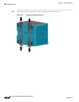
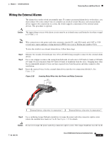
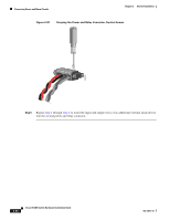
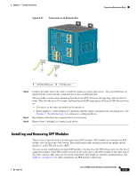
Chapter 2 Switch Installation Connecting Power and Alarm Circuits Wiring the External Alarms The alarm relays on the switch are normally open. To connect an external alarm device to the relays, you must connect two relay contact wires to complete an electrical circuit. Because each external alarm device requires two connections to a relay, the switch supports a maximum of two external alarm devices. This procedure is optional. Caution The input voltage source of the alarm circuits must be an isolated source and limited to less than or equal to 24 VDC, 1 A. Note Wire connections to the power and relay connector, must be UL- and CSA-rated, style 1007 or 1569 twisted-pair copper appliance wiring material (AWM) wire (such as Belden part number 9318). To wire the switch to an external alarm device, follow these steps: Step 1 Step 2 Step 3 Measure two strands of twisted-pair wire (18-to-20 AWG) long enough to connect to the external alarm device. Use a wire stripper to remove the casing from both ends of each wire to 0.25 inch (6.3 mm) ± 0.02 inch (0.5 mm). Do not strip more than 0.27 inch (6.8 mm) of insulation from the wires. Stripping more than the recommended amount of wire can leave exposed wire from the power and relay connector after installation. Insert the exposed wires for the external alarm device into the two connections labeled A. See Figure 2-28. Figure 2-28 Inserting Relay Wires into the Power and Relay Connector 1 2 V RT A A 202029 1 External device, relay wire A connection 1 2 External device, relay wire A connection 2 Step 4 Use a ratcheting torque flathead screwdriver to torque the power and relay connector captive screw (above the installed wire leads) to 2 in-lb. See Figure 2-29 for details. Caution Do not over-torque the power and relay connector captive screws. The torque should not exceed 2 in-lb. OL-13017-01 Cisco IE 3000 Switch Hardware Installation Guide 2-33
-
 1
1 -
2
-
3
-
4
-
5
-
6
-
7
-
8
-
9
-
10
-
11
-
12
-
13
-
14
-
15
-
16
-
17
-
18
-
19
-
20
-
21
-
22
-
23
-
24
-
25
-
26
-
27
-
28
-
29
-
30
-
31
-
32
-
33
-
34
-
35
-
36
-
37
-
38
-
39
-
40
-
41
-
42
-
43
-
44
-
45
-
46
-
47
-
48
-
49
-
50
-
51
-
52
-
53
-
 54
54 -
 55
55 -
 56
56 -
 57
57 -
 58
58 -
 59
59 -
 60
60 -
 61
61 -
 62
62 -
 63
63 -
 64
64 -
65
-
66
-
67
-
68
-
69
-
70
-
71
-
72
-
73
-
74
-
75
-
76
-
77
-
78
-
79
-
80
-
81
-
82
-
83
-
84
-
85
-
86
-
87
-
88
-
89
-
90
-
91
-
92
-
93
-
94
-
95
-
96
-
97
-
98
-
99
-
100
-
101
-
102
-
103
-
104
-
105
-
106
-
107
-
108
-
109
-
110
-
111
-
112
-
113
-
114
-
115
-
116
-
117
-
118
-
119
-
120
-
121
-
122
-
123
-
124
-
125
-
126
-
127
-
128
-
129
-
130
-
131
-
132
-
133
-
134
-
135
-
136
-
137
-
138
-
139
-
140
-
141
-
142
-
143
-
144
-
145
-
146
-
147
-
148
-
149
-
150
-
151
-
152
-
153
-
154
-
155
-
156
-
157
-
158
-
159
-
160
-
161
-
162
-
163
-
164
-
165
-
166
-
167
-
168
-
169
-
170
 |
 |
