Cisco IE-3000-8TC Installation Guide - Page 77
Connecting the Power Converter to a DC Power Source
 |
View all Cisco IE-3000-8TC manuals
Add to My Manuals
Save this manual to your list of manuals |
Page 77 highlights
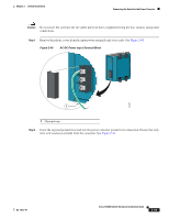
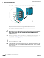
Chapter 2 Switch Installation Connecting the Switch to the Power Converter Connecting the Power Converter to a DC Power Source You can also connect the power converter to a DC power source. The power converter adapts the power source voltage to the 24 VDC that the switch requires. Follow these steps to connect the power converter to a DC power source. Note Use copper conductors only, rated at a minimum temperature of 167°F (75°C). Warning Use twisted-pair supply wires suitable for 86°F (30°C) above surrounding ambient temperature outside the enclosure. Statement 1067 Step 1 Step 2 Step 3 Step 4 Step 5 Step 6 Measure a single length of stranded copper wire long enough to connect the power converter to the earth ground. The wire color might differ depending on the country that you are using it in. For connections from the power converter to earth ground, use shielded 18-AWG stranded copper wire, such as Belden part number 9912 or the equivalent. Measure a length of twisted-pair copper wire long enough to connect the power converter to the DC power source. For DC connections from the power converter to the DC source, use 18-AWG twisted-pair copper wire, such as Belden part number 9344 or the equivalent. Using a 18-gauge wire-stripping tool, strip the ground wire and both ends of the twisted pair wires to 0.25 inch (6.3 mm) ± 0.02 inch (0.5 mm). Do not strip more than 0.27 inch (6.8 mm) of insulation from the wires. Stripping more than the recommended amount of wire can leave exposed wire from the power and relay connector after installation. See Figure 2-9. Connect one end of the stranded copper wire to a grounded bare metal surface, such as a ground bus, a grounded DIN rail, or a grounded bare rack. Insert the other end of the exposed ground wire lead into the earth-ground wire connection on the power converter terminal block. Only wire with insulation should extend from the connection. See Figure 2-45. Tighten the earth-ground wire connection terminal block screw. Note The torque should not exceed 10 in-lb. OL-13017-01 Cisco IE 3000 Switch Hardware Installation Guide 2-51
-
 1
1 -
2
-
3
-
4
-
5
-
6
-
7
-
8
-
9
-
10
-
11
-
12
-
13
-
14
-
15
-
16
-
17
-
18
-
19
-
20
-
21
-
22
-
23
-
24
-
25
-
26
-
27
-
28
-
29
-
30
-
31
-
32
-
33
-
34
-
35
-
36
-
37
-
38
-
39
-
40
-
41
-
42
-
43
-
44
-
45
-
46
-
47
-
48
-
49
-
50
-
51
-
52
-
53
-
54
-
55
-
56
-
57
-
58
-
59
-
60
-
61
-
62
-
63
-
64
-
65
-
66
-
67
-
68
-
69
-
70
-
71
-
 72
72 -
 73
73 -
 74
74 -
 75
75 -
 76
76 -
 77
77 -
 78
78 -
 79
79 -
 80
80 -
 81
81 -
 82
82 -
83
-
84
-
85
-
86
-
87
-
88
-
89
-
90
-
91
-
92
-
93
-
94
-
95
-
96
-
97
-
98
-
99
-
100
-
101
-
102
-
103
-
104
-
105
-
106
-
107
-
108
-
109
-
110
-
111
-
112
-
113
-
114
-
115
-
116
-
117
-
118
-
119
-
120
-
121
-
122
-
123
-
124
-
125
-
126
-
127
-
128
-
129
-
130
-
131
-
132
-
133
-
134
-
135
-
136
-
137
-
138
-
139
-
140
-
141
-
142
-
143
-
144
-
145
-
146
-
147
-
148
-
149
-
150
-
151
-
152
-
153
-
154
-
155
-
156
-
157
-
158
-
159
-
160
-
161
-
162
-
163
-
164
-
165
-
166
-
167
-
168
-
169
-
170
 |
 |
