Cisco IE-3000-8TC Installation Guide - Page 83
Link Status, Transceiver Issues, Port and Interface Settings, Ping End Device, show interfaces - e manual
 |
View all Cisco IE-3000-8TC manuals
Add to My Manuals
Save this manual to your list of manuals |
Page 83 highlights
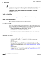
Chapter 3 Troubleshooting Diagnosing Problems Link Status Verify that both sides have link. A single broken wire or one shutdown port can cause one side to show link, but the other side does not have link. A link LED does not guarantee that the cable is fully functional. The cable might have encountered physical stress that causes it to function at a marginal level. If the link light for the port does not come on: • Connect the cable from the switch to a known good device. • Make sure that both ends of the cable are connected to the correct ports. • Verify that both devices have power. • Verify that you are using the correct cable type. See the"Cable and Adapter Specifications" section on page C-4 for more information. • Rule out loose connections. Sometimes a cable appears to be seated, but is not. Disconnect the cable, and then reconnect it. Transceiver Issues Use only Cisco SFP modules on the switch. Each Cisco module has an internal serial EEPROM that is encoded with security information. This encoding provides a way for Cisco to identify and validate that the module meets the requirements for the switch. Check these items: • Bad or wrong SFP module. Exchange the suspect module with a known good module. Verify that the module is supported on this platform. (The switch release notes on Cisco.com list the SFP modules that the switch supports.) • Use the show interfaces privileged EXEC command to verify the port or module error-disabled, disabled, or shutdown status. Re-enable the port if needed. • Make sure that all fiber connections are properly cleaned and securely connected. Port and Interface Settings A cause of port connectivity failure can be a disabled port. Verify that the port or interface is not disabled or powered down for some reason. If a port or interface is manually shut down on one side of the link or the other side, the link does not come up until you re-enable the port. Use the show interfaces privileged EXEC command to verify the port or interface error-disabled, disabled, or shutdown status on both sides of the connection. If needed, re-enable the port or the interface. Ping End Device Test the end device by pinging from the directly connected switch first, and then work your way back port by port, interface by interface, trunk by trunk, until you find the source of the connectivity issue. Make sure that each switch can see the end device MAC address in its content-addressable memory (CAM) table. OL-13017-01 Cisco IE 3000 Switch Hardware Installation Guide 3-3
-
 1
1 -
2
-
3
-
4
-
5
-
6
-
7
-
8
-
9
-
10
-
11
-
12
-
13
-
14
-
15
-
16
-
17
-
18
-
19
-
20
-
21
-
22
-
23
-
24
-
25
-
26
-
27
-
28
-
29
-
30
-
31
-
32
-
33
-
34
-
35
-
36
-
37
-
38
-
39
-
40
-
41
-
42
-
43
-
44
-
45
-
46
-
47
-
48
-
49
-
50
-
51
-
52
-
53
-
54
-
55
-
56
-
57
-
58
-
59
-
60
-
61
-
62
-
63
-
64
-
65
-
66
-
67
-
68
-
69
-
70
-
71
-
72
-
73
-
74
-
75
-
76
-
77
-
 78
78 -
 79
79 -
 80
80 -
 81
81 -
 82
82 -
 83
83 -
 84
84 -
 85
85 -
 86
86 -
 87
87 -
 88
88 -
89
-
90
-
91
-
92
-
93
-
94
-
95
-
96
-
97
-
98
-
99
-
100
-
101
-
102
-
103
-
104
-
105
-
106
-
107
-
108
-
109
-
110
-
111
-
112
-
113
-
114
-
115
-
116
-
117
-
118
-
119
-
120
-
121
-
122
-
123
-
124
-
125
-
126
-
127
-
128
-
129
-
130
-
131
-
132
-
133
-
134
-
135
-
136
-
137
-
138
-
139
-
140
-
141
-
142
-
143
-
144
-
145
-
146
-
147
-
148
-
149
-
150
-
151
-
152
-
153
-
154
-
155
-
156
-
157
-
158
-
159
-
160
-
161
-
162
-
163
-
164
-
165
-
166
-
167
-
168
-
169
-
170
 |
 |
