Cisco IE-3000-8TC Installation Guide - Page 135
B-34, Removing a Bale-Clasp Latch SFP Module by Using a Flat-Blade Screwdriver
 |
View all Cisco IE-3000-8TC manuals
Add to My Manuals
Save this manual to your list of manuals |
Page 135 highlights
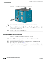
Appendix B Installation In a Hazardous Environment Connecting Destination Ports Figure B-34 Removing a Bale-Clasp Latch SFP Module by Using a Flat-Blade Screwdriver 201867 1 1 Bale clasp Step 5 Step 6 Grasp the SFP module between your thumb and index finger, and carefully remove it from the module slot. Place the removed SFP module in an antistatic bag or other protective environment. Connecting to SFP Modules This section describes how to connect to a fiber-optic SFP port. To connect to an RJ-45 Gigabit Ethernet port instead of a fiber-optic port, see the "Connecting to a Dual-Purpose Port" section on page B-46. For instructions on how to install or remove an SFP module, see the "Installing and Removing SFP Modules" section on page B-42. Follow these steps to connect a fiber-optic cable to an SFP module: Warning Class 1 laser product. Statement 1008 Caution Do not remove the rubber plugs from the SFP module port or the rubber caps from the fiber-optic cable until you are ready to connect the cable. The plugs and caps protect the SFP module ports and cables from contamination and ambient light. Before connecting to the SFP module, be sure that you understand the port and cabling stipulations in the "Preparing for Installation" section on page B-1. See Appendix C, "Cable and Connectors," for information about the LC on the SFP module. OL-13017-01 Cisco IE 3000 Switch Hardware Installation Guide B-45
-
 1
1 -
2
-
3
-
4
-
5
-
6
-
7
-
8
-
9
-
10
-
11
-
12
-
13
-
14
-
15
-
16
-
17
-
18
-
19
-
20
-
21
-
22
-
23
-
24
-
25
-
26
-
27
-
28
-
29
-
30
-
31
-
32
-
33
-
34
-
35
-
36
-
37
-
38
-
39
-
40
-
41
-
42
-
43
-
44
-
45
-
46
-
47
-
48
-
49
-
50
-
51
-
52
-
53
-
54
-
55
-
56
-
57
-
58
-
59
-
60
-
61
-
62
-
63
-
64
-
65
-
66
-
67
-
68
-
69
-
70
-
71
-
72
-
73
-
74
-
75
-
76
-
77
-
78
-
79
-
80
-
81
-
82
-
83
-
84
-
85
-
86
-
87
-
88
-
89
-
90
-
91
-
92
-
93
-
94
-
95
-
96
-
97
-
98
-
99
-
100
-
101
-
102
-
103
-
104
-
105
-
106
-
107
-
108
-
109
-
110
-
111
-
112
-
113
-
114
-
115
-
116
-
117
-
118
-
119
-
120
-
121
-
122
-
123
-
124
-
125
-
126
-
127
-
128
-
129
-
 130
130 -
 131
131 -
 132
132 -
 133
133 -
 134
134 -
 135
135 -
 136
136 -
 137
137 -
 138
138 -
 139
139 -
 140
140 -
141
-
142
-
143
-
144
-
145
-
146
-
147
-
148
-
149
-
150
-
151
-
152
-
153
-
154
-
155
-
156
-
157
-
158
-
159
-
160
-
161
-
162
-
163
-
164
-
165
-
166
-
167
-
168
-
169
-
170
 |
 |
