Cisco IE-3000-8TC Installation Guide - Page 154
Dual-Purpose Ports, Console Port, Cable and Adapter Specifications, SFP Module Cable Specifications
 |
View all Cisco IE-3000-8TC manuals
Add to My Manuals
Save this manual to your list of manuals |
Page 154 highlights
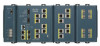
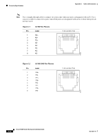
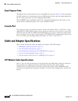
Cable and Adapter Specifications Appendix C Cable and Connectors Dual-Purpose Ports The Ethernet port on a dual-purpose port uses standard RJ-45 connectors. Figure C-2 shows the pinouts. The SFP module slot on a dual-purpose port uses SFP modules for fiber-optic and copper uplink ports. See the switch release notes for a list of supported SFP modules. The auto-MDIX feature is enabled by default. For configuration information for this feature, see the switch software configuration guide or the switch command reference. Console Port The console port uses an 8-pin RJ-45 connector, which is described in Table C-2 and Table C-2. The supplied RJ-45-to-DB-9 adapter cable is used to connect the console port of the switch to a console PC. You need to provide a RJ-45-to-DB-25 female DTE adapter if you want to connect the switch console port to a terminal. You can order a kit (part number ACS-DSBUASYN=) containing that adapter from Cisco. For console port and adapter pinout information, see Table C-2 and Table C-3. Cable and Adapter Specifications These sections describe the cables and adapters used with Cisco IE 3000 switches. • SFP Module Cable Specifications, page C-4 • Two Twisted-Pair Cable Pinouts, page C-5 • Four Twisted-Pair Cable Pinouts for 1000BASE-T Ports, page C-6 • Crossover Cable and Adapter Pinouts, page C-7 • Four Twisted-Pair Cable Pinouts for 1000BASE-T Ports, page C-6 SFP Module Cable Specifications Table C-1 lists the cable specifications for the rugged fiber-optic SFP module connections. Each port must match the wave-length specifications on the other end of the cable, and for reliable communications, the cable must not exceed the required cable length. Copper 1000BASE-T SFP transceivers use standard four twisted-pair, Category 5 or greater cable at lengths up to 328 feet (100 meters). Cisco IE 3000 Switch Hardware Installation Guide C-4 OL-13017-01
-
 1
1 -
2
-
3
-
4
-
5
-
6
-
7
-
8
-
9
-
10
-
11
-
12
-
13
-
14
-
15
-
16
-
17
-
18
-
19
-
20
-
21
-
22
-
23
-
24
-
25
-
26
-
27
-
28
-
29
-
30
-
31
-
32
-
33
-
34
-
35
-
36
-
37
-
38
-
39
-
40
-
41
-
42
-
43
-
44
-
45
-
46
-
47
-
48
-
49
-
50
-
51
-
52
-
53
-
54
-
55
-
56
-
57
-
58
-
59
-
60
-
61
-
62
-
63
-
64
-
65
-
66
-
67
-
68
-
69
-
70
-
71
-
72
-
73
-
74
-
75
-
76
-
77
-
78
-
79
-
80
-
81
-
82
-
83
-
84
-
85
-
86
-
87
-
88
-
89
-
90
-
91
-
92
-
93
-
94
-
95
-
96
-
97
-
98
-
99
-
100
-
101
-
102
-
103
-
104
-
105
-
106
-
107
-
108
-
109
-
110
-
111
-
112
-
113
-
114
-
115
-
116
-
117
-
118
-
119
-
120
-
121
-
122
-
123
-
124
-
125
-
126
-
127
-
128
-
129
-
130
-
131
-
132
-
133
-
134
-
135
-
136
-
137
-
138
-
139
-
140
-
141
-
142
-
143
-
144
-
145
-
146
-
147
-
148
-
 149
149 -
 150
150 -
 151
151 -
 152
152 -
 153
153 -
 154
154 -
 155
155 -
 156
156 -
 157
157 -
 158
158 -
 159
159 -
160
-
161
-
162
-
163
-
164
-
165
-
166
-
167
-
168
-
169
-
170
 |
 |
