Cisco IE-3000-8TC Installation Guide - Page 151
Cable and Connectors, Connector Specifications, 10/100 Ports
 |
View all Cisco IE-3000-8TC manuals
Add to My Manuals
Save this manual to your list of manuals |
Page 151 highlights
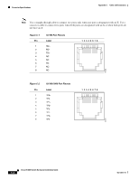
C A P P E N D I X Cable and Connectors This appendix describes the switch ports and the cables and adapters that you use to connect the switch to other devices. Connector Specifications These sections describe the connectors used with the Cisco IE 3000 switch. 10/100 Ports The 10/100 and 10/100/1000 Ethernet ports on switches use standard RJ-45 connectors and Ethernet pinouts with internal crossovers. Figure C-1 and Figure C-2 show the pinouts. The auto-MDIX feature described briefly in this guide is enabled by default. For configuration information for this feature, see the switch software configuration guide or the switch command reference. Connecting to 10BASE-T- and 100BASE-TX-Compatible Devices When connecting the ports to 10BASE-T- and 100BASE-TX-compatible devices, such as servers, workstations, and routers, you can use a two or four twisted-pair, straight-through cable wired for 10BASE-T and 100BASE-TX. Figure C-5 shows the two twisted-pair, straight-through cable schematics. Figure C-7 shows the four twisted-pair, straight-through cable schematics. When connecting the ports to 10BASE-T- and 100BASE-TX-compatible devices, such as switches or repeaters, you can use a two or four twisted-pair, crossover cable. Figure C-6 shows the two twisted-pair, crossover cable schematics. Figure C-8 shows the four twisted-pair, crossover cable schematics. You can use Category 3, 4, or 5 cabling when connecting to 10BASE-T-compatible devices. You must use Category 5 cabling when connecting to 100BASE-TX-compatible devices. Connecting to 1000BASE-T Devices When connecting the ports to 1000BASE-T devices, such as servers, workstations, and routers, you must use a four twisted-pair, Category 5, straight-through cable wired for 10BASE-T, 100BASE-TX, and 1000BASE-T. Figure C-7 shows the straight-through cable schematics. When connecting the ports to other devices, such as switches or repeaters, you must use a four twisted-pair, Category 5, crossover cable. Figure C-8 shows the crossover cable schematics. OL-13017-01 Cisco IE 3000 Switch Hardware Installation Guide C-1
-
 1
1 -
2
-
3
-
4
-
5
-
6
-
7
-
8
-
9
-
10
-
11
-
12
-
13
-
14
-
15
-
16
-
17
-
18
-
19
-
20
-
21
-
22
-
23
-
24
-
25
-
26
-
27
-
28
-
29
-
30
-
31
-
32
-
33
-
34
-
35
-
36
-
37
-
38
-
39
-
40
-
41
-
42
-
43
-
44
-
45
-
46
-
47
-
48
-
49
-
50
-
51
-
52
-
53
-
54
-
55
-
56
-
57
-
58
-
59
-
60
-
61
-
62
-
63
-
64
-
65
-
66
-
67
-
68
-
69
-
70
-
71
-
72
-
73
-
74
-
75
-
76
-
77
-
78
-
79
-
80
-
81
-
82
-
83
-
84
-
85
-
86
-
87
-
88
-
89
-
90
-
91
-
92
-
93
-
94
-
95
-
96
-
97
-
98
-
99
-
100
-
101
-
102
-
103
-
104
-
105
-
106
-
107
-
108
-
109
-
110
-
111
-
112
-
113
-
114
-
115
-
116
-
117
-
118
-
119
-
120
-
121
-
122
-
123
-
124
-
125
-
126
-
127
-
128
-
129
-
130
-
131
-
132
-
133
-
134
-
135
-
136
-
137
-
138
-
139
-
140
-
141
-
142
-
143
-
144
-
145
-
 146
146 -
 147
147 -
 148
148 -
 149
149 -
 150
150 -
 151
151 -
 152
152 -
 153
153 -
 154
154 -
 155
155 -
 156
156 -
157
-
158
-
159
-
160
-
161
-
162
-
163
-
164
-
165
-
166
-
167
-
168
-
169
-
170
 |
 |
