Cisco IE-3000-8TC Installation Guide - Page 55
Installing the Switch in a Rack, Step 2
 |
View all Cisco IE-3000-8TC manuals
Add to My Manuals
Save this manual to your list of manuals |
Page 55 highlights
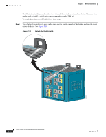
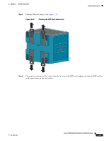
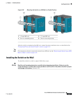
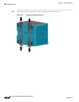
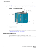
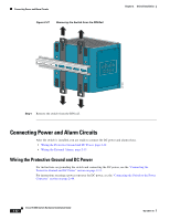
Chapter 2 Switch Installation Installing the Switch Step 2 Step 3 Rotate all feet to the recessed positions so that the switch can mount flat on the wall or panel. See Figure 2-22. Position the rear panel of the switch against the wall or a panel in the desired location. See Figure 2-24. Figure 2-24 Mounting the Switch on the Wall 1 201833 Step 4 Place a number-10 screw that you provide through each DIN rail latch, and screw them into the wall. 1 Wall After the switch is mounted on the wall or panel, connect the power and alarm wires, as described in the "Connecting Power and Alarm Circuits" section on page 2-32. Installing the Switch in a Rack You can use an optional DIN rail adapter kit (available through Cisco, part number STK-RACKMNT-2955=) to mount the switch in a 19-inch rack. The rack-mounting kit comes with a DIN rail adapter and screws to attach the adapter to the rack. Ask your Cisco representative for details. OL-13017-01 Cisco IE 3000 Switch Hardware Installation Guide 2-29
-
 1
1 -
2
-
3
-
4
-
5
-
6
-
7
-
8
-
9
-
10
-
11
-
12
-
13
-
14
-
15
-
16
-
17
-
18
-
19
-
20
-
21
-
22
-
23
-
24
-
25
-
26
-
27
-
28
-
29
-
30
-
31
-
32
-
33
-
34
-
35
-
36
-
37
-
38
-
39
-
40
-
41
-
42
-
43
-
44
-
45
-
46
-
47
-
48
-
49
-
 50
50 -
 51
51 -
 52
52 -
 53
53 -
 54
54 -
 55
55 -
 56
56 -
 57
57 -
 58
58 -
 59
59 -
 60
60 -
61
-
62
-
63
-
64
-
65
-
66
-
67
-
68
-
69
-
70
-
71
-
72
-
73
-
74
-
75
-
76
-
77
-
78
-
79
-
80
-
81
-
82
-
83
-
84
-
85
-
86
-
87
-
88
-
89
-
90
-
91
-
92
-
93
-
94
-
95
-
96
-
97
-
98
-
99
-
100
-
101
-
102
-
103
-
104
-
105
-
106
-
107
-
108
-
109
-
110
-
111
-
112
-
113
-
114
-
115
-
116
-
117
-
118
-
119
-
120
-
121
-
122
-
123
-
124
-
125
-
126
-
127
-
128
-
129
-
130
-
131
-
132
-
133
-
134
-
135
-
136
-
137
-
138
-
139
-
140
-
141
-
142
-
143
-
144
-
145
-
146
-
147
-
148
-
149
-
150
-
151
-
152
-
153
-
154
-
155
-
156
-
157
-
158
-
159
-
160
-
161
-
162
-
163
-
164
-
165
-
166
-
167
-
168
-
169
-
170
 |
 |
