Cisco IE-3000-8TC Installation Guide - Page 148
B-45, AC/DC Power Input Terminal Block Wire Connections to a DC Source
 |
View all Cisco IE-3000-8TC manuals
Add to My Manuals
Save this manual to your list of manuals |
Page 148 highlights
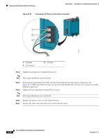
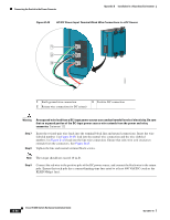
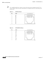
Connecting the Switch to the Power Converter Appendix B Installation In a Hazardous Environment Figure B-45 AC/DC Power Input Terminal Block Wire Connections to a DC Source 1 2 3 202301 1 Earth ground wire connection 2 Return wire connection (to DC return) 3 Positive DC connection Warning An exposed wire lead from a DC-input power source can conduct harmful levels of electricity. Be sure that no exposed portion of the DC-input power source wire extends from the power and relay connector. Statement 122 Step 7 Step 8 Insert the twisted-pair wire leads into the terminal block line and neutral connections. Insert the wire (labeled number 1 in Figure B-45) lead into the neutral wire connection and the wire (labeled number 2 in Figure B-45) lead into the line wire connection. Ensure that only wire with insulation extends from the connectors. See Figure B-45. Tighten the line and neutral terminal block screws. Note The torque should not exceed 10 in-lb. Step 9 Connect the red wire to the positive pole of the DC power source, and connect the black wire to the return pole. Ensure that each pole has a current-limiting-type fuse rated to at least 600 VAC/DC (such as the KLKD Midget fuse). B-58 Cisco IE 3000 Switch Hardware Installation Guide OL-13017-01
-
 1
1 -
2
-
3
-
4
-
5
-
6
-
7
-
8
-
9
-
10
-
11
-
12
-
13
-
14
-
15
-
16
-
17
-
18
-
19
-
20
-
21
-
22
-
23
-
24
-
25
-
26
-
27
-
28
-
29
-
30
-
31
-
32
-
33
-
34
-
35
-
36
-
37
-
38
-
39
-
40
-
41
-
42
-
43
-
44
-
45
-
46
-
47
-
48
-
49
-
50
-
51
-
52
-
53
-
54
-
55
-
56
-
57
-
58
-
59
-
60
-
61
-
62
-
63
-
64
-
65
-
66
-
67
-
68
-
69
-
70
-
71
-
72
-
73
-
74
-
75
-
76
-
77
-
78
-
79
-
80
-
81
-
82
-
83
-
84
-
85
-
86
-
87
-
88
-
89
-
90
-
91
-
92
-
93
-
94
-
95
-
96
-
97
-
98
-
99
-
100
-
101
-
102
-
103
-
104
-
105
-
106
-
107
-
108
-
109
-
110
-
111
-
112
-
113
-
114
-
115
-
116
-
117
-
118
-
119
-
120
-
121
-
122
-
123
-
124
-
125
-
126
-
127
-
128
-
129
-
130
-
131
-
132
-
133
-
134
-
135
-
136
-
137
-
138
-
139
-
140
-
141
-
142
-
 143
143 -
 144
144 -
 145
145 -
 146
146 -
 147
147 -
 148
148 -
 149
149 -
 150
150 -
 151
151 -
 152
152 -
 153
153 -
154
-
155
-
156
-
157
-
158
-
159
-
160
-
161
-
162
-
163
-
164
-
165
-
166
-
167
-
168
-
169
-
170
 |
 |
