D-Link DFL-300 User Manual
D-Link DFL-300 - Security Appliance Manual
 |
UPC - 790069240751
View all D-Link DFL-300 manuals
Add to My Manuals
Save this manual to your list of manuals |
D-Link DFL-300 manual content summary:
- D-Link DFL-300 | User Manual - Page 1
FIREWALL VPN ROUTER User's Manual - 1 - Doc. No.: 120602-01 - D-Link DFL-300 | User Manual - Page 2
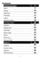
Contents Administration 5 Admin 6 Setting 10 Date/Time 16 Language 17 Logout 18 Software Update 19 Configuration 20 Interface 21 Multiple NAT 25 Hack Alert 32 Route Table 33 DHCP 37 DNS Proxy 39 Dynamic DNS 44 Address 49 Interface 50 Internal Group 54 External - D-Link DFL-300 | User Manual - Page 3
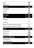
DMZ DMZ Group Service Pre-defined Custom Group Schedule Policy Outgoing Incoming External To DMZ & Internal to DMZ DMZ To External & DMZ To Internal VPN Autokey IKE PPTP Server PPTP Client Content filtering URL Blocking General Blocking Virtual Server - 3 - 66 70 74 75 76 80 84 88 89 97 103 109 115 - D-Link DFL-300 | User Manual - Page 4
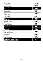
Mapped IP Virtual Server LOG Traffic Log Event Log Log Report Alarm Traffic Alarm Event Alarm Statistics Status Interface Status ARP Table DHCP Clients Setup Examples 138 142 150 151 154 157 160 161 164 167 168 168 169 170 171 - 4 - - D-Link DFL-300 | User Manual - Page 5
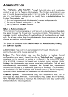
IP address of a SMTP (Simple Mail Transfer protocol) Server is required. Up to two e-mail addresses can be entered for the alert notifications. Software Update: Administrators may visit distributor's web site to download the latest firmware. Administrators may update the FIREWALL VPN ROUTER firmware - D-Link DFL-300 | User Manual - Page 6
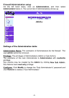
Firewall Administration setup On the left hand menu, click on Administration, and then select Administrator below it. The current list of Administrator(s) shows up. Settings of the Administration table: Administrator Name: The username of Administrators for the firewall. The user admin cannot be - D-Link DFL-300 | User Manual - Page 7
a new Sub Administrator. Step 2. In the Add New Sub Administrator window: Sub Admin Name: enter the username of new Sub Admin. Password: enter a password for the new Sub Admin. Confirm Password: enter the password again. Step 3. Click OK to add the user or click Cancel to cancel the addition. - 7 - - D-Link DFL-300 | User Manual - Page 8
Modify in the Configure field. The Modify Administrator Password window will appear. Enter in the required information: Password: enter original password. New Password: enter new password Confirm Password: enter the new password again. Click OK to confirm password change or click Cancel to cancel it - D-Link DFL-300 | User Manual - Page 9
Removing a Sub Administrator: Step 1. In the Administration table, locate the Administrator name you want to edit, and click on the Remove option in the Configure field. Step 2. The Remove confirmation pop-up box will appear. Step 3. Click OK to remove that Sub Admin or click Cancel to cancel. - 9 - - D-Link DFL-300 | User Manual - Page 10
the firewall back to default factory settings. Entering the Settings window: Click Setting in the Administrator menu to enter the Settings window. The Firewall Configuration settings will be shown on the screen. Exporting FIREWALL VPN ROUTER Firewall settings: Step 1. Under Firewall Configuration - D-Link DFL-300 | User Manual - Page 11
on the Browse button next to Import System Settings. When the Choose File pop-up window appears, select the file to which contains the saved Firewall Settings, then click OK. Step 2. Click OK to import the file into the Firewall or click Cancel to cancel importing. - 11 - - D-Link DFL-300 | User Manual - Page 12
Restoring Factory Default Settings: Step 1. Select Reset Factory Settings under Firewall Configuration. Step 2. Click OK at the bottom-right of the screen to restore the factory settings. - 12 - - D-Link DFL-300 | User Manual - Page 13
function will enable the Firewall to send e-mail alerts to the System Administrator when the network is being attacked by hackers or when emergency conditions occur. Step 2. SMTP Server IP: Enter SMTP server's IP address. Step 3. E-Mail Address 1: Enter the first e-mail address to receive the alarm - D-Link DFL-300 | User Manual - Page 14
To-Firewall Packets Log Select this option to the FIREWALL VPN ROUTER's To-Firewall Packets Log. Once this function is enabled, every packet to this appliance will be recorded for system manager to trace. - 14 - - D-Link DFL-300 | User Manual - Page 15
Reboot Select this option to the FIREWALL VPN ROUTER's Firewall Reboot. Once this function is enabled, the firewall will be rebooted. Step 1. Click Setting in the Administration menu to enter the settings window. Step 2. Reboot Firewall:Click Reboot. Step 3. A confirmation pop-up box will appear - D-Link DFL-300 | User Manual - Page 16
System →Date/Time. Step 2. Click the down arrow b to select the offset time from GMT. Step 3. Enter the Server IP Address or Server name with which you want to synchronize. Step 4. Update system clock every minutes You can set the interval time to synchronize with outside servers. If you set it to - D-Link DFL-300 | User Manual - Page 17
Language The software provides Traditional Chinese Version , Simplified Chinese Version and English version for you to choose. Step 1. Click Language. Step 2. Select the language version you want Traditional Chinese Version,Simplified Chinese Version and English version). Step 3. Click OK to change - D-Link DFL-300 | User Manual - Page 18
Logout the firewall Select this option to the FIREWALL VPN ROUTER's Logout the firewall; this function protects your system while you are away Step 1. Click Logout the firewall. Step 2. Click OK to logout or click Cancel to discard the change. - 18 - - D-Link DFL-300 | User Manual - Page 19
Software Update Under Software Update, the admin may update the FIREWALL VPN ROUTER's software with a newer software. - 19 - - D-Link DFL-300 | User Manual - Page 20
is System Configuration? In this section, the Administrator can: (1) Set up the internal, external and DMZ IP addresses (2) Set up the Multiple NAT (3) Set up the Firewall detecting functions (4) Set up a static route (5) Set up the DHCP Server (6) Set up DNS Proxy (7) Set up Dynamic DNS Note: After - D-Link DFL-300 | User Manual - Page 21
network will not be routable on the Internet. IP Address: The private IP address of the Firewall's internal network is the IP address of the Internal (LAN) port of the FIREWALL VPN ROUTER. The default IP address is 192.168.1.1. Note: The IP Address of Internal Interface and the DMZ Interface is - 21 - D-Link DFL-300 | User Manual - Page 22
: This is the netmask of the internal network. The default netmask of the FIREWALL VPN ROUTER is 255.255.255.0. Ping: Select this to allow the internal network to ping the IP Address of the Firewall. If set to enable, the FIREWALL VPN ROUTER will respond to ping packets from the internal network - D-Link DFL-300 | User Manual - Page 23
the FIREWALL VPN ROUTER always requires a username and password to enter the WebUI. For Dynamic IP Address (Cable Modem User): This option is for users who are automatically assigned an IP address by their ISP, such as cable modem users. The following fields apply: IP Address: The dynamic IP address - D-Link DFL-300 | User Manual - Page 24
the IP Address of the Firewall. This will allow people from the Internet to be able to ping the Firewall. If set to enable, the FIREWALL VPN ROUTER to be configured from a user on the Internet. Keep in mind that the FIREWALL VPN ROUTER always requires a username and password to enter the WebUI. DMZ - D-Link DFL-300 | User Manual - Page 25
NAT, after completing the settings, each department use the different WAN IP Address to connect to the internet. The settings of each department are as the following Service IP Address:192.168.2.1 Subnet Mask:255.255.255.0 Default Gateway:192.168.2.11 The other departments are also set by groups - D-Link DFL-300 | User Manual - Page 26
NAT settings Click Multiple NAT in the Configuration menu to enter Multiple NAT window. Multiple NAT Global port interface IP Address:Global port IP Address. Local port interface IP Address:Local port IP Address and subnet Mask. Modify:Modify the settings of Multiple NAT. Click Modify to modify the - D-Link DFL-300 | User Manual - Page 27
to add Multiple NAT. Step 3. Enter the IP Address in the website name column of the new window. 1.1 Global port interface IP Address: Select Global port IP Address. 3.2 Local port interface IP Address: Enter Local port IP Address. 3.3 Subnet Mask:Enter Local port subnet Mask. Step 4. Click OK to add - D-Link DFL-300 | User Manual - Page 28
Multiple NAT Step 1. Click Multiple NAT in the Configuration menu to enter Multiple NAT window. Step 2. Find the IP Address you want to modify and click Modify Step 3. Enter the new IP Address in Modify Multiple NAT window. Step 4. Click the OK button below to change the setting or click Cancel to - D-Link DFL-300 | User Manual - Page 29
Delete Multiple NAT Step 1.Click Multiple NAT in the Configuration menu to enter Multiple NAT window. Step 2.Find the IP Address you want to delete and click Delete. Step 3.A confirmaion pop-up box will appear, click OK to delete the setting or click Cancel to discard changes. - 29 - - D-Link DFL-300 | User Manual - Page 30
Administrator can enable the FIREWALL VPN ROUTER's auto detect functions in this section. When abnormal conditions occur, the Firewall will send an e- server computers continuously to block or cut down all the connections of the servers. These attacks will prevent valid users from connecting to the - D-Link DFL-300 | User Manual - Page 31
to the Administrator. The default UDP flood threshold is set users of the network in Spoof attacks. They use a fake identity to try to pass through the Firewall System and invade the network. Filter IP Source Route Option: Each IP packet can carry an optional field that specifies the replying address - D-Link DFL-300 | User Manual - Page 32
packets with the same source and destination addresses, the same source port and destination port, and when SYN on the TCP header is marked. Enable this function to detect such abnormal packets. Default Packet Deny: Denies all packets from passing the Firewall. A packet can pass only when there is - D-Link DFL-300 | User Manual - Page 33
left side menu bar, and then click Route Table below it. The Route Table window appears, in which current route settings are shown. Route Table functions: Interface: Destination network, internal or external networks. Destination IP: IP address of destination network. NetMask: Netmask of destination - D-Link DFL-300 | User Manual - Page 34
Adding a new Static Route: Step 1. In the Route Table window, click the New Entry button. Step 2. In the Add New Static Route window, enter new static route information. Step 3. In the Interface field's pull-down menu, choose the network to connect (Internal, External or DMZ). Step 4. Click OK to - D-Link DFL-300 | User Manual - Page 35
Modifying a Static Route: Step 1. In the Route Table menu, find the route to edit and click the corresponding Modify option in the Configure field. Step 2. In the Modify Static Route window, modify the necessary routing addresses. Step 3. Click OK to apply changes or click Cancel to cancel it. - 35 - D-Link DFL-300 | User Manual - Page 36
Removing a Static Route: Step 1. In the Route Table window, find the route to remove and click the corresponding Remove option in the Configure field. Step 2. In the Remove confirmation pop-up box, click OK to confirm removing or click Cancel to cancel it. - 36 - - D-Link DFL-300 | User Manual - Page 37
hand side menu bar, and then click DHCP below it. The DHCP window appears in which current DHCP settings are shown on the screen. Dynamic IP Address functions: Subnet: Internal network's subnet NetMask: Internal network's netmask Gateway: Internal network's gateway - D-Link DFL-300 | User Manual - Page 38
. Step 4. Client IP Address Range 1: Enter the starting and the ending IP address dynamically assigning to DHCP clients. Step 5. Client IP Address Range 2: Enter the starting and the ending IP address dynamically assigning to DHCP clients. (Optional) Step 6. Click OK to enable DHCP support. - 38 - - D-Link DFL-300 | User Manual - Page 39
DNS Proxy function to make the FIREWALL VPN ROUTER Firewall act as a DNS Server for the Internal and DMZ network. All DNS requests to a specific Domain Name will be routed to the firewall's IP address. For example, let's say an organization has their mail server (i.e., mail.dfl300.com) in the DMZ - D-Link DFL-300 | User Manual - Page 40
DNS Proxy window will appear. Below is the information needed for setting up the DNS Proxy: • Domain Name: The domain name of the server • Virtual IP Address: The virtual IP address respective to DNS Proxy • Configure: modify or remove each DNS Proxy policy - 40 - - D-Link DFL-300 | User Manual - Page 41
Adding a new DNS Proxy: Step 1: Click on the New Entry button and the Add New DNS Proxy window will appear. Step 2: Fill in the appropriate settings for the domain name and virtual IP address. Step 3: Click OK to save the policy or Cancel to cancel. - 41 - - D-Link DFL-300 | User Manual - Page 42
Modifying a DNS Proxy: Step 1: In the DNS Proxy window, find the policy to be modified and click the corresponding Modify option in the Configure field. Step 2: Make the necessary changes needed. Step 3: Click OK to save changes or click on Cancel to cancel modifications. - 42 - - D-Link DFL-300 | User Manual - Page 43
Removing a DNS Proxy: Step 1: In the DNS Proxy window, find the policy to be removed and click the corresponding Remove option in the Configure field. Step 2: A confirmation pop-up box will appear, click OK to remove the DNS Proxy or click Cancel. - 43 - - D-Link DFL-300 | User Manual - Page 44
name: Enter the password provided by ISP. WAN IP Address: IP Address of the WAN port. Modify: Modify dynamic DNS settings. Click Modify to change the DNS parameters; click Delete to delete the settings. 2. How to use dynamic DNS: The firewall provides 3 service providers, users have to register - D-Link DFL-300 | User Manual - Page 45
- 45 - - D-Link DFL-300 | User Manual - Page 46
the new window. Service providers: Select service providers. Register: to the service providers' website. WAN IP Address: IP Address of the WAN port. automatically fill in the external IP: Check to automatically fill in the external IP.。 User Name:Enter the registered user name. Password: Enter the - D-Link DFL-300 | User Manual - Page 47
Modify dynamic DNS Step 1: Click Dynamic DNS in the Configuration menu to enter Dynamic DNS window. Step 2: Find the item you want to change and click Modify. Step 3: Enter the new information in the Modify Dynamic DNS window. Step 4: Click OK to change the settings or click Cancel to discard - D-Link DFL-300 | User Manual - Page 48
Delete Dynamic DNS Step 1: Click Dynamic DNS in the Configuration menu to enter Dynamic DNS window. Step 2: Find the item you want to change and click Delete. Step 3: A confirmation pop-up box will appear, click OK to delete the settings or click Cancel to discard changes. - 48 - - D-Link DFL-300 | User Manual - Page 49
Address The FIREWALL VPN ROUTER Office Firewall allows the Administrator to set Interface addresses of the Internal network, Internal network group, External network, External network group, DMZ and DMZ group. What is the Address Table? An IP address in the Address Table can be an address of a - D-Link DFL-300 | User Manual - Page 50
Internal Entering the Internal window: Step 1. Click Internal under the Address menu to enter the Internal window. The current setting information such as the name of the internal network, IP and Netmask addresses will show on the screen. - 50 - - D-Link DFL-300 | User Manual - Page 51
Adding a new Internal Address: Step 1. In the Internal window, click the New Entry button. Step 2. In the Add New Address window, enter the settings of a new internal network address. Step 3. Click OK to add the specified internal network or click Cancel to cancel the changes. - 51 - - D-Link DFL-300 | User Manual - Page 52
name of the network to be modified. Click the Modify option in its corresponding Configure field. The Modify Address window appears on the screen immediately. Step 2. In the Modify Address window, fill in the new addresses. Step 3. Click OK to save changes or click Cancel to discard changes. - 52 - - D-Link DFL-300 | User Manual - Page 53
Removing an Internal Address: Step 1. In the Internal window, locate the name of the network to be removed. Click the Remove option in its corresponding Configure field. Step 2. In the Remove confirmation pop-up box, click OK to remove the address or click Cancel to discard changes. - 53 - - D-Link DFL-300 | User Manual - Page 54
Internal Group Entering the Internal Group window: The Internal Addresses may be combined together to become a group. Click Internal Group under the Address menu to enter the Internal Group window. The current setting information for the Internal network group appears on the screen. - 54 - - D-Link DFL-300 | User Manual - Page 55
Internal Group window, click the New Entry button to enter the Add New Address Group window. Step 2. In the Add New Address Group window: Available Address: list the names of all the members of the internal network. Selected Address: list the names to be assigned to the new group. Name: enter the - D-Link DFL-300 | User Manual - Page 56
Modify option in the Configure field. Step 2. A window displaying the information of the selected group appears: Available Address: list names of all members of the Internal network. Selected Address: list names of members which have been assigned to this group. Step 3. Add members: Select names in - D-Link DFL-300 | User Manual - Page 57
Removing an Internal Group: Step 1. In the Internal Group window, locate the group to be removed and click its corresponding Remove option in the Configure field. Step 2. In the Remove confirmation pop-up box, click OK to remove the group or click Cancel to discard changes. - 57 - - D-Link DFL-300 | User Manual - Page 58
External Entering the External window: Click External under the Address menu to enter the External window. The current setting information, such as the name of the External network, IP and Netmask addresses will show on the screen. - 58 - - D-Link DFL-300 | User Manual - Page 59
Adding a new External Address: Step 1. In the External window, click the New Entry button. Step 2. In the Add New Address window, enter the settings for a new external network address. Step 3. Click OK to add the specified external network or click Cancel to discard changes. - 59 - - D-Link DFL-300 | User Manual - Page 60
: Step 1. In the External table, locate the name of the network to be modified and click the Modify option in its corresponding Configure field. Step 2. The Modify Address window will appear on the screen immediately. In the Modify Address window, fill in new addresses. Step 3. Click OK to save - D-Link DFL-300 | User Manual - Page 61
Removing an External Address: Step 1. In the External table, locate the name of the network to be removed and click the Remove option in its corresponding Configure field. Step 2. In the Remove confirmation pop-up box, click OK to remove the address or click Cancel to discard changes. - 61 - - D-Link DFL-300 | User Manual - Page 62
External Group Entering the External Group window: Click the External Group under the Address menu bar to enter the External window. The current settings for the external network group(s) will appear on the screen. - 62 - - D-Link DFL-300 | User Manual - Page 63
. Step 3. Add members: Select the names to be added in the Available Address list, and click the Add>> button to add them to the Selected Address list. Step 4. Remove members: Select the names to be removed in the Selected Address list, and click the - D-Link DFL-300 | User Manual - Page 64
button in the Configure field. Step 2. A window displaying the information of the selected group appears: Available Address: list the names of all the members of the external network. Selected Address: list the names of the members that have been assigned to this group. Step 3. Add members: Select - D-Link DFL-300 | User Manual - Page 65
Removing an External Group: Step 1. In the External Group window, locate the group to be removed and click its corresponding Modify option in the Configure field. Step 2. In the Remove confirmation pop-up box, click OK to remove the group or click Cancel to discard changes. - 65 - - D-Link DFL-300 | User Manual - Page 66
DMZ Entering the DMZ window: Click DMZ under the Address menu to enter the DMZ window. The current setting information such as the name of the internal network, IP, and Netmask addresses will show on the screen. - 66 - - D-Link DFL-300 | User Manual - Page 67
Adding a new DMZ Address: Step 1. In the DMZ window, click the New Entry button. Step 2. In the Add New Address window, enter the settings for a new DMZ address. Step 3. Click OK to add the specified DMZ or click Cancel to discard changes. - 67 - - D-Link DFL-300 | User Manual - Page 68
Modifying a DMZ Address: Step 1. In the DMZ window, locate the name of the network to be modified and click the Modify option in its corresponding Configure field. Step 2. In the Modify Address window, fill in new addresses. Step 3. Click OK on save the changes or click Cancel to discard changes. - - D-Link DFL-300 | User Manual - Page 69
Removing a DMZ Address: Step 1. In the DMZ window, locate the name of the network to be removed and click the Remove option in its corresponding Configure field. Step 2. In the Remove confirmation pop-up box, click OK to remove the address or click Cancel to discard changes. - 69 - - D-Link DFL-300 | User Manual - Page 70
DMZ Group Entering the DMZ Group window: Click DMZ Group under the Address menu to enter the DMZ window. The current settings information for the DMZ group appears on the screen. - 70 - - D-Link DFL-300 | User Manual - Page 71
a DMZ Group: Step 1. In the DMZ Group window, click the New Entry button. Step 2. In the Add New Address Group window: Available Address: list names of all members of the DMZ. Selected Address: list names to assign to a new group. Step 3. Name: enter a name for the new group. Step 4. Add members - D-Link DFL-300 | User Manual - Page 72
Modify button in the Configure field. Step 2. A window displaying information about the selected group appears: Available Address: list the names of all the members of the DMZ. Selected Address: list the names of the members that have been assigned to this group. Step 3. Add members: Select - D-Link DFL-300 | User Manual - Page 73
Removing a DMZ Group: Step 1. In the DMZ Group window, locate the group to be removed and click its corresponding Remove option in the Configure field. Step 2. In the Remove confirmation pop-up box, click OK to remove the group. - 73 - - D-Link DFL-300 | User Manual - Page 74
. Users then can connect to servers and other computers through these available network services. What is Service? TCP and UDP protocols support varieties of services, and each service consists of a TCP Port or UDP port number, such as TELNET (23), SMTP (21), POP3 (110), etc. The FIREWALL VPN ROUTER - D-Link DFL-300 | User Manual - Page 75
Pre-defined Entering a Pre-defined window: Click Service on the menu bar on the left side of the window. Click Predefined under it. A window will appear with a list of services and their associated IP addresses. This list cannot be modified. - 75 - - D-Link DFL-300 | User Manual - Page 76
Custom Entering the Custom window: Click Service on the menu bar on the left side of the window. Click Custom under it. A window will appear with a table showing all services currently defined by the Administrator. - 76 - - D-Link DFL-300 | User Manual - Page 77
. Step 2 In the new service table: New Service Name: This will be the name referencing the new service. Protocol: Enter the network protocol type to be used, such as TCP, UDP, or Other (please enter the number for the protocol type). Client Port: enter the range of port number of new clients. Server - D-Link DFL-300 | User Manual - Page 78
: Step 1. In the Custom table, locate the name of the service to be modified. Click its corresponding Modify option in the Configure field. Step 2. A table showing the current settings of the selected service appears on the screen Step 3. Enter the new values. Step 4. Click OK to accept editing - D-Link DFL-300 | User Manual - Page 79
Removing Custom Services: Step 1. In the Custom window, locate the service to be removed. Click its corresponding Remove option in the Configure field. Step 2. In the Remove confirmation pop-up box, click OK to remove the selected service or click Cancel to cancel action. - 79 - - D-Link DFL-300 | User Manual - Page 80
Group Accessing the Group window: Click Service in the menu bar on the left hand side of the window. Click Group under it. A window will appear with a table displaying current service group settings set by the Administrator. - 80 - - D-Link DFL-300 | User Manual - Page 81
Groups: Step 1. In the Group window, click the New Entry button. In the Add Service Group window, the following fields will appear: Available Services: list all the available services. Selected Services: list services to be assigned to the new group. Step 2. Enter the new group name in the group - D-Link DFL-300 | User Manual - Page 82
(modify) group window the following fields are displayed: Available Services: lists all the available services. Selected Services: list services that have been assigned to the selected group. Step 3. Add new services: Select services in the Available Services list, and then click the Add>> button to - D-Link DFL-300 | User Manual - Page 83
Removing Service Groups: Step 1. In the Group window, locate the service group to be removed and click its corresponding Remove option in the Configure field. Step 2. In the Remove confirmation pop-up box, click OK to remove the selected service group or click Cancel to cancel removing. - 83 - - D-Link DFL-300 | User Manual - Page 84
FIREWALL VPN ROUTER Office Firewall allows the Administrator to configure a schedule for policies to take affect. By creating a schedule, the Administrator is allowing the Firewall an organization may only want the Firewall to allow the internal network users to access the Internet during work hours - D-Link DFL-300 | User Manual - Page 85
Adding a new Schedule: Step 1: Click on the New Entry button and the Add New Schedule window will appear. Step 2: Schedule Name: Fill in a name for the new schedule. Period 1: Configure the start and stop time for the days of the week that the schedule will be active. Step 3: Click Ok to save the - D-Link DFL-300 | User Manual - Page 86
Modifying a Schedule: Step 1: In the Schedule window, find the policy to be modified and click the corresponding Modify option in the Configure field. Step 2: Make needed changes. Step 3: Click OK to save changes. - 86 - - D-Link DFL-300 | User Manual - Page 87
Removing a Schedule: Step 1: In the Schedule window, find the policy to be removed and click the corresponding Remove option in the Configure field. Step 2: A confirmation pop-up box will appear, click on OK to remove the schedule. - 87 - - D-Link DFL-300 | User Manual - Page 88
source IP addresses, source ports, destination IP addresses, and destination ports. Control policies decide whether packets from different network objects, network services, and applications are able to pass through the Firewall. What is Policy? The FIREWALL VPN ROUTER uses policies to filter - D-Link DFL-300 | User Manual - Page 89
menu, or all the External (WAN) network addresses. Service: specify services provided by external network servers. Action: control actions to permit or reject/deny packets from internal networks to external network travelling through the Firewall. Option: specify the monitoring functions on packets - D-Link DFL-300 | User Manual - Page 90
external networks defined in the External section of the Address window. To create a new destination address, please go to the External section under the Address menu. Service: Specified services provided by external network servers. These are services/application that are allowed to pass from the - D-Link DFL-300 | User Manual - Page 91
Action: Select Permit or Deny from the drop down list to allow or reject the packets travelling between the source network and the destination network. Logging: Select Enable to enable flow monitoring. Statistics: Select Enable to enable flow statistics. Alarm Threshold: set a maximum flow rate (in - D-Link DFL-300 | User Manual - Page 92
the drop-down list for source or destination address, go to the section where the selections are setup. (Source Address→ Internal of Address menu; Destination Address → External of Address menu; Service→[Pre-defined],[Custom] or Group under Service). Step 3: Click OK to do confirm modification or - D-Link DFL-300 | User Manual - Page 93
Removing the Outgoing Policy: Step 1. In the Outgoing policy section, locate the name of the policy desired to be removed and click its corresponding Remove option in the Configure field. Step 2. In the Remove confirmation dialogue box, click OK to remove the policy or click Cancel to cancel - D-Link DFL-300 | User Manual - Page 94
Enabled Monitoring function: Log: If Logging is enabled in the outgoing policy, the FIREWALL VPN ROUTER will log the traffic and event passing through the Firewall. The Administrator can click Log on the left menu bar to get the flow and event logs of the specified policy. Note: System Administrator - D-Link DFL-300 | User Manual - Page 95
Alarm: If Logging is enabled in the outgoing policy, the FIREWALL VPN ROUTER will log the traffic alarms and event alarms passing through the Firewall. The Administrator can click Alarm on the left menu to get the logs of flow and event alarms of the specified policy. Note: The Administrator - D-Link DFL-300 | User Manual - Page 96
Statistics: If Statistics is enabled in the outgoing policy, the FIREWALL VPN ROUTER will display the flow statistics passing through the Firewall. Note: The Administrator can also get flow statistics in Statistics. Please refer to Statistics in Chapter 11 for more details. - 96 - - D-Link DFL-300 | User Manual - Page 97
are IP Mapping addresses or Virtual server network addresses created in Virtual Server menu. Service: services supported by Virtual Servers (or Mapped IP). Action: control actions to permit or deny packets from external networks to Virtual Server/Mapped IP travelling through the FIREWALL VPN ROUTER - D-Link DFL-300 | User Manual - Page 98
Option: specify the monitoring functions on packets from external networks to Virtual Server/Mapped IP travelling through the Firewall. Configure: modify settings or remove incoming policy. Move: this sets the priority of the policies, number 1 being the highest priority. - 98 - - D-Link DFL-300 | User Manual - Page 99
the names of IP mapping addresses specified in the Mapped IP or the Virtual Server sections of Virtual Server menu. To create a new destination address, please go to the Virtual Server menu. (Please refer to Chapter 8 for Virtual Server for details) Service: Specified services provided by internal - D-Link DFL-300 | User Manual - Page 100
be sent if flow rates are higher than the specified value. Step 3: Click OK to add new policy or click Cancel to cancel adding new incoming policy. - 100 - - D-Link DFL-300 | User Manual - Page 101
Modifying Incoming Policy: Step 1: In the Incoming window, locate the name of policy desired to be modified and click its corresponding Modify option in the Configure field. Step 2: In the Modify Policy window, fill in new settings. Step 3: Click OK to save modifications or click Cancel to cancel - D-Link DFL-300 | User Manual - Page 102
Removing an Incoming Policy: Step 1: In the Incoming window, locate the name of policy desired to be removed and click its corresponding [Remove] in the Configure field. Step 2: In the Remove confirmation window, click Ok to remove the policy or click Cancel to cancel removing. - 102 - - D-Link DFL-300 | User Manual - Page 103
External To DMZ table will show up displaying currently defined policies. The Address menu, or all the external network addresses. Destination: destination networks, which are addresses specified in DMZ section of the Address menu and Mapped IP addresses of the Virtual Server menu. Service: services supported - D-Link DFL-300 | User Manual - Page 104
Action: control actions, to permit or deny packets from external networks to DMZ travelling through the FIREWALL VPN ROUTER. Option: specify the monitoring functions of packets from external network to DMZ network travelling through Firewall. Configure: modify settings or remove policies. - 104 - - D-Link DFL-300 | User Manual - Page 105
will also contain Mapped IP addresses from the Virtual Server menu that were created for the DMZ network. To create a new destination address, please go to the Virtual Server menu. (Please refer to the sections entitled Address and Virtual Server for details) Service: Select a service from drop down - D-Link DFL-300 | User Manual - Page 106
entitled Services for details) Action: Select Permit or Deny from the drop down list to allow or reject the packets travelling from the specified external network to - D-Link DFL-300 | User Manual - Page 107
Modifying an External to DMZ policy: Step 1: In the External To DMZ window, locate the name of policy desired to be modified and click its corresponding Modify option in the Configure field. Step 2: In the Modify Policy window, fill in new settings. Step 3: Click OK to do save modifications. - 107 - - D-Link DFL-300 | User Manual - Page 108
Removing an External To DMZ Policy: Step 1: In the External To DMZ window, locate the name of policy desired to be removed and click its corresponding Remove option in the Configure field. Step 2: In the Remove confirmation pop-up box, click OK to remove the policy. - 108 - - D-Link DFL-300 | User Manual - Page 109
section of the Address window. Destination: destination networks, which is the external network address Service: services supported by Servers of external networks. Action: control actions, to permit or deny packets from the DMZ network to external networks travelling through the FIREWALL VPN - 109 - D-Link DFL-300 | User Manual - Page 110
ROUTER. Option: specify the monitoring functions on packets from the DMZ network to external networks travelling through the Firewall. Configure: modify settings or remove policies Move: this sets the priority of the policies, number 1 being the highest priority. - 110 - - D-Link DFL-300 | User Manual - Page 111
external network from the drop down list. The drop down list lists names of addresses defined in External section of the Address menu. To add a new destination address, please go to External section of the Address menu. Service: Select a service from drop down list. The drop down list will contain - D-Link DFL-300 | User Manual - Page 112
Action: Select Permit or Deny from the drop down list to allow or reject the packets travelling from the specified DMZ network to the external network. Logging: select Enable to enable flow monitoring. Statistics: click Enable to enable flow statistics. Alarm Threshold: set a maximum flow rate (in - D-Link DFL-300 | User Manual - Page 113
or add selections in the drop-down list, go to the section where the selections are setup. (Source Address→DMZ of Address; Destination Address→External, Service→Pre-defined Service, Custom or Group under Service.) Step 3: Click OK to save modifications or click Cancel to cancel modifications. - 113 - D-Link DFL-300 | User Manual - Page 114
Removing a DMZ To External Policy: Step 1. In the DMZ To External window, locate the name of policy desired to be removed and click its corresponding Remove option in the Configure field. Step 2. In the Remove confirmation dialogue box, click OK. - 114 - - D-Link DFL-300 | User Manual - Page 115
VPN The FIREWALL VPN ROUTER Firewall's VPN (Virtual Private Network) is set by the System Administrator. The System Administrator can add, modify or remove VPN settings. What is VPN? To set up a Virtual Private Network (VPN), you don't need to configure an Access Policy to enable encryption. Just - D-Link DFL-300 | User Manual - Page 116
two sites creating the tunnel. Gateway IP: The external interface IP address of the remote Firewall. Destination Subnet: Destination network subnet. PSK/RSA: The IKE VPN must be defined with a Preshared Key. The Key may be up to 128 bytes long. Status: Connect/Disconnect or Connecting/Disconnecting - D-Link DFL-300 | User Manual - Page 117
is used to provide confidentially to IP datagrams. ESP-Encryption Algorithm: The FIREWALL VPN ROUTER auto-selects 56 bit DES-CBC or 168-bit Triple DES-CBC encryption algorithm. The default algorithm is 168-bit Triple DES-CBC. ESP-Authentication Method: The FIREWALL VPN ROUTER autoselects MD5 or SHA - D-Link DFL-300 | User Manual - Page 118
correct settings, click on the Connect option in the Configure field. The Status field will change to indicate Connecting. If the remote Firewall is set up correctly with the VPN active, the VPN connection will be made between the two Firewalls and the Status field will change to Connect. - 118 - - D-Link DFL-300 | User Manual - Page 119
Removing Autokey IKE: Step 1. Locate the name of the Autokey IKE desired to be removed and click its corresponding Delete option in the Configure field. Step 2. In the Remove confirmation pop-up box, click OK to remove the Autokey IKE or click Cancel to cancel deleting. - 119 - - D-Link DFL-300 | User Manual - Page 120
PPTP Client connection. User Name: Displays the PPTP Client user's name for authentication. Client IP:Displays the PPTP Client's IP address for authentication.。 Uptime:Displays the connection time between PPTP Server and Client. Status:Displays current connection status between PPTP Server and PPTP - D-Link DFL-300 | User Manual - Page 121
VPN→PPTP Server. Step 2. Click【Modify】after the Client IP Range. Step 3. In the【Modify Server Design 】Window, enter appropriate settings. Disable PPTP:Check to disable PPTP Server. Enable PPTP:Check to enable PPTPServer. 1.Encyption: the default is set to disabled. 2.Client IP Range:Enter the IP - D-Link DFL-300 | User Manual - Page 122
. User name: Specify the PPTP client. This should be unique. Password: Specify the PPTP client password. Remote Client: Single Machine: Check to connect to single computer. Multi-Machine: Check to allow multiple computers connected to the PPTP server. IP Address:Enter the PPTP Client IP address - D-Link DFL-300 | User Manual - Page 123
Step 3. Click OK to save modifications or click Cancel to cancel modifications - 123 - - D-Link DFL-300 | User Manual - Page 124
Modifying PPTP Server Step 1. Select VPN→PPTP Server. Step 2. In the【PPTP Server】window, find the PPTP server that you want to modify. Click 【Configure】and click 【Modify】. Step 3. Enter appropriate settings. Step 4. Click OK to save modifications or click Cancel to - D-Link DFL-300 | User Manual - Page 125
Removing PPTP Server Step 1. Select VPN→PPTP Server. Step 2. In the【PPTP Server】window, find the PPTP server that you want to modify. Click 【Configure】and click 【remove】. Step 3. Click OK to remove the PPTP server or click Cancel to exit without removal. - 125 - - D-Link DFL-300 | User Manual - Page 126
1. Select VPN→PPTP Client. Server Address:Display the PPTP Server IP addresses.. User Name:Displays the PPTP Client user's name for authentication. Client IP:Displays the PPTP Client's IP address for authentication.。 Uptime:Displays the connection time between PPTP Server and Client. Status:Displays - D-Link DFL-300 | User Manual - Page 127
Client Step 1. Select VPN→PPTP Client. User name: Specify the PPTP client. This should be unique. Password: Specify the PPTP client password. Server Address: Enter the PPTP Server's IP address. Remote Client: Single Machine: Check to connect to single computer. Multi-Machine: Check to allow multiple - D-Link DFL-300 | User Manual - Page 128
Modifying PPTP Client Step 1. Select VPN→PPTP Client. Step 2. In the【PPTP Client】window, find the PPTP server that you want to modify. Click 【Configure】and click 【Modify】. Step 3. Enter appropriate settings. Step 4. Click OK to save modifications or click Cancel to - D-Link DFL-300 | User Manual - Page 129
Removing PPTP Client Step 1. Select VPN→PPTP Client. Step 2. In the【PPTP Client】window, find the PPTP client that you want to modify. Click 【Configure】and click 【remove】. Step 3. Click OK to remove the PPTP client or click Cancel to exit without removal. - 129 - - D-Link DFL-300 | User Manual - Page 130
Content filtering Content filtering includes URL Blocking and general filtering. Content Filtering includes「URL Blocking」and 「General Blocking URL Blocking:The device manager can use a complete domain name, key word, "〜" or "*" to make rules for specific websites. (二)General Blocking:To let Popup、 - D-Link DFL-300 | User Manual - Page 131
URL Blocking The Administrator may setup URL Blocking to prevent Internal network users from accessing a specific website on the Internet. Any web request coming from an Internal network computer to a blocked website will receive a blocked message instead of the website. Entering the URL blocking - D-Link DFL-300 | User Manual - Page 132
Adding a URL Blocking policy: Step 1: Step 2: Step 3: After clicking New Entry, the Add New Block String window will appear. Enter the URL of the website to be blocked. Click OK to add the policy. Click Cancel to discard changes. - 132 - - D-Link DFL-300 | User Manual - Page 133
Modifying a URL Blocking policy: Step 1: Step 2: Step 3: In the URL Blocking window, find the policy to be modified and click the corresponding Modify option in the Configure field. Make the necessary changes needed. Click on OK to save changes or click on Cancel to cancel modifications. - 133 - - D-Link DFL-300 | User Manual - Page 134
option in the Configure field. A confirmation pop-up box will appear, click on OK to remove the policy or click on Cancel to discard changes. Blocked URL site: When a user from the Internal network tries to access a blocked URL, the error below will appear. - 134 - - D-Link DFL-300 | User Manual - Page 135
in or keep them out. Step 1: Click Content Filtering in the menu. Step 2: 【General Blocking】detective functions. Popup filtering:Prevent the pop-up boxes appearing. ActiveX filtering:Prevent ActiveX packets. Java filtering:Prevent Java packets. Cookie filtering:Prevent Cookie packets. Step 3: After - D-Link DFL-300 | User Manual - Page 136
service to the external networks, is located in the internal networks, outside users can't directly connect to the server by using the server's private IP address. The FIREWALL VPN ROUTER Firewall's Virtual Server can solve this problem. A virtual server has set the real IP address of the Firewall - D-Link DFL-300 | User Manual - Page 137
virtual server to the private internal IP address of the physical server that supports the services. Therefore users from the external network can access servers of the internal network by requesting the service from the IP address provided by Virtual Server. - 137 - - D-Link DFL-300 | User Manual - Page 138
are the two methods to translate the real IP into private IP. Mapped IP maps IP in one-to-one fashion; that means, all services of one real external IP address is mapped to one private internal IP address. Entering the Mapped IP window: Click Mapped IP under the Virtual Server menu bar and the - D-Link DFL-300 | User Manual - Page 139
button the Add New Mapped IP window will appear. External IP: select the external public IP address to be mapped. Internal IP: enter the internal private IP address or DMZ IP address which will be mapped 1-to-1 to the external IP address. Step 2. Click OK to add new IP Mapping or click Cancel to - D-Link DFL-300 | User Manual - Page 140
: Step 1. In the Mapped IP table, locate the Mapped IP desired to be modified and click its corresponding Modify option in the Configure field. Step 2. Enter settings in the Modify Mapped IP window. Step 3. Click OK to save change or click Cancel to cancel. Note: A Mapped IP cannot be modified if it - D-Link DFL-300 | User Manual - Page 141
Removing a Mapped IP: Step 1. In the Mapped IP table, locate the Mapped IP desired to be removed and click its corresponding Remove option in the Configure field. Step 2. In the Remove confirmation pop-up window, click Ok to remove the Mapped IP or click Cancel to cancel. - 141 - - D-Link DFL-300 | User Manual - Page 142
to private IP addresses of the internal network. This is done to provide services or applications defined in the Service menu to enter into the internal network. Unlike a mapped IP which binds an external IP to an Internal/DMZ IP, virtual server binds external IP ports to Internal IP ports. - 142 - D-Link DFL-300 | User Manual - Page 143
the click here to configure button and the Add new Virtual Server IP window appears and asks for an IP address from the external network. Step 3. Select an IP address from the drop-down list of available external network IP addresses. Note: If the drop-down list contains only (Disable), there is no - D-Link DFL-300 | User Manual - Page 144
When Disable appears in the drop-down list, no Virtual Server can be added. - 144 - - D-Link DFL-300 | User Manual - Page 145
under the Virtual Server menu bar. A new window appears displaying the IP address and service of the specified virtual server. Step 2. Click on the Virtual Server's IP Address button at the top of the screen. Step 3. Choose a new IP address from the drop-down list. Step 4. Click OK to save new - D-Link DFL-300 | User Manual - Page 146
the corresponding Virtual Server option under the Virtual Server menu bar. A new window displaying the virtual server's IP address and service appears on the screen. Step 2. Click the Virtual Server's IP Address button at the top of the screen. Step 3. Select Disable in the drop-down list in. Step - D-Link DFL-300 | User Manual - Page 147
has already been set up with an IP address, click the New Service button in the table. Step 2. In the Virtual Server Configurations window: Virtual Server IP: displays the external IP address assigned to the Virtual Server External Service Port: select the port number that the virtual server will - D-Link DFL-300 | User Manual - Page 148
the Virtual Server configurations: Step 1. In the Virtual Server window's service table, locate the name of the service desired to be modified and click its corresponding Modify option in the modified or removed if it has been assigned to the destination address of any Incoming policies. - 148 - - D-Link DFL-300 | User Manual - Page 149
: Step 1. In the Virtual Server window's service table, locate the name of the service desired to be removed and click its corresponding Remove option in the Configure field. Step 2. In the Remove confirmation pop-up box, click Ok to remove the service or click Cancel to cancel removing. - 149 - D-Link DFL-300 | User Manual - Page 150
Log The FIREWALL VPN ROUTER Office Firewall supports traffic logging and event logging to monitor and record services, connection times, and the source and destination network address. The Administrator may also download the log files for backup purposes. The Administrator mainly uses the Log menu - D-Link DFL-300 | User Manual - Page 151
Log: The table in the Traffic Log window displays current System statuses: Time: The start time of the connection. Source: IP address of the source network of the specific connection. Destination: IP address of the destination network of the specific connection. Protocol & Port: Protocol type - D-Link DFL-300 | User Manual - Page 152
Downloading the Traffic Logs: The Administrator can backup the traffic logs regularly by downloading it to the computer. Step 1. In the Traffic Log window, click the Download Logs button at the bottom of the screen. Step 2. Follow the File Download pop-up window to save the traffic logs into a - D-Link DFL-300 | User Manual - Page 153
Clearing the Traffic Logs: The Administrator may clear on-line logs to keep just the most updated logs on the screen. Step 1. In the Traffic Log window, click the Clear Logs button at the bottom of the screen. Step 2. In the Clear - D-Link DFL-300 | User Manual - Page 154
Log When the FIREWALL VPN ROUTER Firewall detects events, the Administrator can get the details, such as time and description of the events from the Event Logs. Entering the Event Log window: Click the Event Log option under the Log menu and the Event Log window will appear. The table in the Event - D-Link DFL-300 | User Manual - Page 155
Downloading the Event Logs: Step 1. In the Event Log window, click the Download Logs button at the bottom of the screen. Step 2. Follow the File Download pop-up window to save the event logs into a specific directory on the hard drive. - 155 - - D-Link DFL-300 | User Manual - Page 156
Clearing the Event Logs: The Administrator may clear on-line event logs to keep just the most updated logs on the screen. Step 1. In the Event Log window, click the Clear Logs button at the bottom of the screen. Step 2. In the Clear - D-Link DFL-300 | User Manual - Page 157
Log Log Report. Step 2. Log Mail Configuration:When the Log Mail files accumulated up to 300Kbytes, router will notify administrator by email with the traffic log and event log.。 Note: Before enabling this and the Event Log simultaneously to the server which supports Syslog function. - 157 - - D-Link DFL-300 | User Manual - Page 158
to receive the alarm notification. Click OK. Step 2. Go to LOG Log Report. Check to enable Log Mail Support. Click OK. System Settings/Enable Syslog Message Step 3. Check to enable Syslog Message. Enter the Host IP Address and Host Port number to receive the Syslog message. Step 4. Click OK. - 158 - - D-Link DFL-300 | User Manual - Page 159
Disable Log Mail Support & Syslog Message Step 1. Go to LOG Click OK. Step 2. Go to LOG Click OK. Log Report. Uncheck to disable Log Mail Support. Log Report. Uncheck to disable Settings Message. - 159 - - D-Link DFL-300 | User Manual - Page 160
checks whether the traffic for a policy exceeds its threshold value and adds a record to the traffic alarm file if it does. Event alarm: When Firewall detects attacks from hackers, it writes attacking data in the event alarm file and sends an e-mail alert to the Administrator to take emergency steps - D-Link DFL-300 | User Manual - Page 161
Alarm option below Alarm menu to enter the Traffic Alarm window. The table in the Traffic Alarm window displays the current traffic alarm logs for connections Name of the destination network of the specific connection. Service: Service of the specific connection. Traffic: Traffic (in Kbytes/Sec) of - D-Link DFL-300 | User Manual - Page 162
Clearing the Traffic Alarm Logs: Step 1. In the Traffic Alarm window, click the Clear Logs button at the bottom of the screen. Step 2. In the Clear Logs pop-up box, click Ok to clear the logs or click Cancel to cancel. - 162 - - D-Link DFL-300 | User Manual - Page 163
Downloading the Traffic Alarm Logs: The Administrator can back up traffic alarm logs regularly and download it to a file on the computer. Step 1. In the Traffic Alarm window, click the Download Logs button on the bottom of the screen. Step 2. Follow the File Download pop-up box to save the traffic - D-Link DFL-300 | User Manual - Page 164
Event Alarm Entering the Event Alarm window: Click the Event Alarm option below the Alarm menu to enter the Event Alarm window. The table in Event Alarm window displays current traffic alarm logs for connections. Time: log time. Event: event descriptions. - 164 - - D-Link DFL-300 | User Manual - Page 165
Clearing Event Alarm Logs: The Administrator may clear on-line logs to keep the most updated logs on the screen. Step 1. In the Event Alarm window, click the Clear Logs button at the bottom of the screen. Step 2. In the Clear Logs pop-up box, click OK. - 165 - - D-Link DFL-300 | User Manual - Page 166
Downloading the Event Alarm Logs: The Administrator can back up event alarm logs regularly by downloading it to a file on the computer. Step 1. In the Event Alarm window, click the Download Logs button at the bottom of the screen. Step 2. Follow the File Download pop-up box to save the event alarm - D-Link DFL-300 | User Manual - Page 167
FIREWALL VPN ROUTER Office Firewall for statistics of packets and data which passes across the Firewall that pass through the Firewall by control policies setup by the Administrator. How name of source address. Destination: the name of destination address. Service: the service requested. Action: - D-Link DFL-300 | User Manual - Page 168
the FIREWALL VPN ROUTER displays the status information about the Firewall. Status will display the network information from the Configuration menu. The Administrator may also use Status to check the DHCP lease time and MAC addresses for computers connected to the Firewall. Interface Status Entering - D-Link DFL-300 | User Manual - Page 169
: Click on Status in the menu bar, and then click ARP Table below it. A window will appear displaying a table with IP addresses and their corresponding MAC addresses. For each computer on the Internal, External, and DMZ network that replies to an ARP packet, the FIREWALL VPN ROUTER will list them - D-Link DFL-300 | User Manual - Page 170
: Click on Status in the menu bar, and then click on DHCP Clients below it. A window will appear displaying the table of DHCP clients that are connected to the FIREWALL VPN ROUTER. The table will list host computers on the Internal network that obtain its IP address from the Firewall's DHCP server - D-Link DFL-300 | User Manual - Page 171
Setup Examples Example 1: Allow the Internal network to be able to access the Internet Example 2: The Internal network can only access Yahoo.com website Example 3: Outside users network and have the Internet (External) users access the server through IP Mapping Please see the explanation of the - D-Link DFL-300 | User Manual - Page 172
Step 4 When the following screen appears, the setup is completed. - 172 - - D-Link DFL-300 | User Manual - Page 173
access Yahoo.com website. Step 1. Enter the External window under the Address menu. Step 2. Click the New Entry button. Step 3. In the Add New Address window, enter relating parameters. Step 4. Click OK to end the address table setup. Step 5. Go to the Outgoing window under the Policy menu. Step - D-Link DFL-300 | User Manual - Page 174
Step 8. When the following screen appears, the setup is completed. - 174 - - D-Link DFL-300 | User Manual - Page 175
Example 3: Outside users can access the internal FTP server through Virtual Servers Step 1. Enter Virtual Server under the Virtual Server menu. Step 2. Click the 'click here to configure' button. Step 3. Select an External IP address, then click OK. Step 4. Click the New Service button on the bottom - D-Link DFL-300 | User Manual - Page 176
Step 7. Go to the Incoming window under the Policy menu, and then click on the New Entry button. Step 8. In the Add New Policy window, set each parameter, then click OK. - 176 - - D-Link DFL-300 | User Manual - Page 177
Step 9. An Incoming FTP policy should now be created. - 177 - - D-Link DFL-300 | User Manual - Page 178
users access the server through IP Mapping Step 1. Enter the Mapped IP window under the Virtual Server menu. Step 2. Click the New Entry button. Step 3. In the Add New IP Mapping window, enter each parameter, and then click OK. Step 4. When the following screen appears, the IP Mapping setup is - D-Link DFL-300 | User Manual - Page 179
Step 8. Open all the services. (ANY) Step 9. The setup is completed. - 179 -
-
 1
1 -
 2
2 -
 3
3 -
 4
4 -
 5
5 -
 6
6 -
 7
7 -
8
-
9
-
10
-
11
-
12
-
13
-
14
-
15
-
16
-
17
-
18
-
19
-
20
-
21
-
22
-
23
-
24
-
25
-
26
-
27
-
28
-
29
-
30
-
31
-
32
-
33
-
34
-
35
-
36
-
37
-
38
-
39
-
40
-
41
-
42
-
43
-
44
-
45
-
46
-
47
-
48
-
49
-
50
-
51
-
52
-
53
-
54
-
55
-
56
-
57
-
58
-
59
-
60
-
61
-
62
-
63
-
64
-
65
-
66
-
67
-
68
-
69
-
70
-
71
-
72
-
73
-
74
-
75
-
76
-
77
-
78
-
79
-
80
-
81
-
82
-
83
-
84
-
85
-
86
-
87
-
88
-
89
-
90
-
91
-
92
-
93
-
94
-
95
-
96
-
97
-
98
-
99
-
100
-
101
-
102
-
103
-
104
-
105
-
106
-
107
-
108
-
109
-
110
-
111
-
112
-
113
-
114
-
115
-
116
-
117
-
118
-
119
-
120
-
121
-
122
-
123
-
124
-
125
-
126
-
127
-
128
-
129
-
130
-
131
-
132
-
133
-
134
-
135
-
136
-
137
-
138
-
139
-
140
-
141
-
142
-
143
-
144
-
145
-
146
-
147
-
148
-
149
-
150
-
151
-
152
-
153
-
154
-
155
-
156
-
157
-
158
-
159
-
160
-
161
-
162
-
163
-
164
-
165
-
166
-
167
-
168
-
169
-
170
-
171
-
172
-
173
-
174
-
175
-
176
-
177
-
178
-
179
 |
 |

- 1 -
FIREWALL VPN ROUTER
User’s Manual
Doc. No.: 120602-01