Dell Force10 E1200i Installing and Maintaining the E1200i System
Dell Force10 E1200i Manual
 |
View all Dell Force10 E1200i manuals
Add to My Manuals
Save this manual to your list of manuals |
Dell Force10 E1200i manual content summary:
- Dell Force10 E1200i | Installing and Maintaining the E1200i System - Page 1
Installing and Maintaining the E1200i System - Dell Force10 E1200i | Installing and Maintaining the E1200i System - Page 2
damage to hardware or loss of data if instructions are not followed. WARNING: A WARNING indicates a potential for property damage, personal injury, or death. Information in this publication is subject to change without notice. © 2010 Dell Force10. All rights reserved. Reproduction of these materials - Dell Force10 E1200i | Installing and Maintaining the E1200i System - Page 3
Unpacking the E1200 System 23 Installing the Equipment Rack Shelf Bar 23 Standard Front Chassis Mounting 24 Installing the Chassis into an Equipment Cabinet 25 6 Installing Fan Trays 7 Installing AC Power Supplies Securing the Chassis Ground 30 Installing Power Supplies 30 AC Power Supply and - Dell Force10 E1200i | Installing and Maintaining the E1200i System - Page 4
dell.com | support.dell.com DC Power Supply LEDs 46 Installing Switch Fabric Modules ( AC Power Supplies 58 Remove an AC Power Supply in a non-redundant installation 59 Remove an AC Power Supply in a redundant installation 59 Removing and Replacing DC Power Supplies 59 Remove a DC Power Supply - Dell Force10 E1200i | Installing and Maintaining the E1200i System - Page 5
Prompt 69 C Alarms Power Supplies and Alarms 76 AC Power Supplies and Alarms 77 SFMs and Alarms 77 D System Specifications E1200i AC Chassis Physical Design 79 E1200i AC System Power Requirements 80 E1200i DC Chassis Physical Design 80 E1200i DC System Power Requirements 80 Environmental - Dell Force10 E1200i | Installing and Maintaining the E1200i System - Page 6
www.dell.com | support.dell.com 6 | Contents - Dell Force10 E1200i | Installing and Maintaining the E1200i System - Page 7
Dell Force10 E1200 chassis, as well as instructions to install fan trays, power supplies, route processor modules (RPMs), switch fabric modules (SFMs), and line cards. This guide also includes instructions for removing and installing field-replaceable parts, including power supplies for both the AC - Dell Force10 E1200i | Installing and Maintaining the E1200i System - Page 8
dell.com | support.dell in AC-powered systems: AC power cords are secured to the power inlet using the provided brackets. The power E1200 system, refer to the following documents: • FTOS Configuration Guide for the E-Series • FTOS Command Reference for the E-Series • E-Series Network Operations Guide - Dell Force10 E1200i | Installing and Maintaining the E1200i System - Page 9
The Dell Force10 E1200 system is a carrier-class, high-capacity aggregation router. The 16-slot modular system provides two slots dedicated for Route Processor Modules (RPMs) and 14 slots for line cards with Layer 2 switching and Layer 3 and routing capabilities. Operating Overview The E1200 system - Dell Force10 E1200i | Installing and Maintaining the E1200i System - Page 10
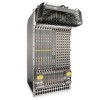
www.dell.com | support.dell.com Figure 2-1. E1200i AC Chassis Front View Line Card Slots Switch Fabric Module (SFM) Air Vents 10 | The E1200 System Cable Management System Line Card Slots RPM 1 Blank (BLNK) Air Filter AC Power Supply AC Power Plug - Dell Force10 E1200i | Installing and Maintaining the E1200i System - Page 11
Figure 2-2. E1200 AC Chassis Rear View Installed Fan Tray locking screw Empty Fan Tray with Self-closing Door Ground Connection Ground Connection The E1200 System | 11 - Dell Force10 E1200i | Installing and Maintaining the E1200i System - Page 12
www.dell.com | support.dell.com Figure 2-3. E1200i DC Chassis Front View Line Card Slots Cable Management System Line Card Slots RPM 1 Switch Fabric Module (SFM) DC Power Supply Air Vents 12 | The E1200 System Blank (BLNK) DC Power Supply Air Filter - Dell Force10 E1200i | Installing and Maintaining the E1200i System - Page 13
Door Ground Connection Ground Connection Table 2-1. E1200 Hardware Component Operating Requirements Summary Component Backplane (factory installed) Air filter (factory installed) Fan trays RPMs Line cards SFMs AC Power Supply DC Power Supply Cable management system Cable management system cover - Dell Force10 E1200i | Installing and Maintaining the E1200i System - Page 14
tray operability AC Power Supply and Fan Operability Test on page 31 DC Power Supply and Fan Operability Test on page 38 7 Install card components: • RPM(s) and line cards • SFMs Installing Line Cards and RPMs on page 42 Installing Switch Fabric Modules (SFMs) on page 46 8 Connect network cable - Dell Force10 E1200i | Installing and Maintaining the E1200i System - Page 15
Criteria on page 15 • Rack Mounting on page 16 • Cabinet Placement on page 16 • Power on page 16 • Fans and Airflow on page 17 • Storing Components on page 17 For complete E1200 System Specifications, refer to Appendix D, System Specifications, on page 79. Site Selection Criteria Before you - Dell Force10 E1200i | Installing and Maintaining the E1200i System - Page 16
, power supplies, and cards. Power At a minimum, the E1200 requires either 2 AC Power Supplies or 1 DC PEM to operate. CAUTION: You cannot power the system with both types of power supply module installed. The system must contain only one type of power module, either AC or DC. CAUTION: The E1200i AC - Dell Force10 E1200i | Installing and Maintaining the E1200i System - Page 17
tray. • Operate the E1200 system with two fan trays. For instructions on replacing a fan tray, refer to Removing and Replacing Fan Trays on page 57. Storing Components CAUTION: Do not transport a chassis with components (line cards, power supplies, RPMs, Fan Trays, Power Supply, or SFMs) installed - Dell Force10 E1200i | Installing and Maintaining the E1200i System - Page 18
18 | Site Preparation www.dell.com | support.dell.com - Dell Force10 E1200i | Installing and Maintaining the E1200i System - Page 19
AC Chassis This chapter provides instructions to rack mount your E1200 system into a standard 19-inch or 23-inch equipment rack. It contains the following sections: • Unpacking the E1200 the power supplies, fan trays, air filter, or cards until the chassis is installed. WARNING: The E1200 AC shipping - Dell Force10 E1200i | Installing and Maintaining the E1200i System - Page 20
www.dell.com | support.dell.com Figure 4-1. Rack Shelf Bar UP UP FN To Chassis Mounting NOTE: Dell Force10 recommends that you install and operate the E1200 system in a standard 19-inch or 23inch equipment rack. Install the E1200 system after you and EMI seals. 20 | Installing the AC Chassis - Dell Force10 E1200i | Installing and Maintaining the E1200i System - Page 21
and tighten to secure the chassis in the rack. Installing the Chassis into an Equipment Cabinet Install the E1200 system after you secure the rack shelf bar. Load the chassis in the lower half of the or forklift, align the rack-mount holes with the cabinet holes. Installing the AC Chassis | 21 - Dell Force10 E1200i | Installing and Maintaining the E1200i System - Page 22
www.dell.com | support.dell.com Step Task 4 Insert rack mounting screws in the holes that are not obscured by the metal chassis shipping cover. Tighten the shipping cover. 6 Insert the remaining mounting screws and tighten to secure the chassis in the cabinet. 22 | Installing the AC Chassis - Dell Force10 E1200i | Installing and Maintaining the E1200i System - Page 23
instructions to rack mount your E1200 system into a standard 19-inch or 23-inch equipment rack. It contains the following sections: • Unpacking the E1200 Do not unpack the power supplies, fan trays, air filter, or cards until the chassis is installed. WARNING: The E1200 DC shipping containers each - Dell Force10 E1200i | Installing and Maintaining the E1200i System - Page 24
www.dell.com | support.dell.com Figure 5-1. Rack Shelf Bar UP UP FN To install a equipment rack Standard Front Chassis Mounting NOTE: Dell Force10 recommends that you install and operate the E1200 system in a standard 19-inch or 23inch equipment rack. Install the E1200 system after you secure the - Dell Force10 E1200i | Installing and Maintaining the E1200i System - Page 25
cover. 6 Insert the remaining rack-mounting screws and tighten to secure the chassis in the rack. Installing the Chassis into an Equipment Cabinet Install the E1200 system after you secure the rack shelf bar. Load the chassis in the lower half of the cabinet to avoid it becoming top-heavy. Make - Dell Force10 E1200i | Installing and Maintaining the E1200i System - Page 26
www.dell.com | support.dell.com Step Task 5 Loosen and remove the screws attaching the chassis shipping cover. Remove the shipping cover. 6 Insert the remaining mounting screws and tighten to secure the chassis in the cabinet. 26 | Installing the DC Chassis - Dell Force10 E1200i | Installing and Maintaining the E1200i System - Page 27
operation, do not operate the chassis with only one fan tray for more than 30 minutes. WARNING: Install the fan trays before you supply power to the system. WARNING: Electrostatic discharge (ESD) damage can occur when components are mishandled. Always wear an ESD-preventative wrist or foot-heal - Dell Force10 E1200i | Installing and Maintaining the E1200i System - Page 28
dell.com Figure 6-2. Fan Tray screw latch Install the fan trays after the chassis is installed securely in the equipment rack. Access the fan tray slots from the rear side of the chassis. To ensure proper temperature and airflow control, all six fan trays must be installed before you supply power - Dell Force10 E1200i | Installing and Maintaining the E1200i System - Page 29
the LEDs will indicate status while the On/Standby switch is in Standby. Figure 7-1. E1200i AC Power Supply Shelf Power Supplies On/Standby Switch AC-Cord Retainer Safety Cover AC-0 AC-1 AC-2 AC-3 AC-4 AC-5 AC-0 AC-3 AC-1 AC-4 AC-2 AC-5 WARNING - HIGH LEAKAGE CURRENT. EARTH CONNECTION - Dell Force10 E1200i | Installing and Maintaining the E1200i System - Page 30
stopped rotating. When replacing a power supply, to avoid arcing and discoloration of the supply and the chassis pins, please wait for the fans to stop rotating before reinserting the supply Power Cord Requirements If using a power cord other then a Dell Force10 supplied power cord, the cord must - Dell Force10 E1200i | Installing and Maintaining the E1200i System - Page 31
On/Standby switch, located on the left side of plug AC-0, is in the Standby (up) position (Figure 7-1). 2 Loosen the cord retainers locking screws (if needed) and tilt the AC-cord retainer up approximately 15o and gently slide the cover away from the chassis. 3 Slide the power supplies into - Dell Force10 E1200i | Installing and Maintaining the E1200i System - Page 32
www.dell.com | support.dell.com WARNING: Prevent exposure and contact with hazardous voltages. Do not attempt to operate this system without the AC-cord Retainer. • Your power cables connect to an appropriate AC power supply in a manner that complies with your local electrical codes. For AC systems - Dell Force10 E1200i | Installing and Maintaining the E1200i System - Page 33
SF4L-SFMC Force10 Networks Force10 Networks Force10 Networks Force10 Networks Force10 Networks Force10 Networks Force10 Networks Force10 Networks Force10 Networks online 8-2 is used in both the E1200 and E1200i DC chassis. Figure 8-2. E1200i DC PEM FN00101lp Installing DC Power Supplies | 33 - Dell Force10 E1200i | Installing and Maintaining the E1200i System - Page 34
.dell.com | support.dell.com Figure 8-3. E1200 PEM Front Panel Studs PEM interlock lever Latch Release Status -48/-60Vdc 150A, 7200VA CC-E1200-PWR-DC Over-current protector FN00102lp Locking screws Cable and Connector Requirements You must provide your own cables to connect to a remote power - Dell Force10 E1200i | Installing and Maintaining the E1200i System - Page 35
the following steps to install a DC PEM: Step Task 1 Make sure that the remote power source (the circuit breaker panel) is in the OFF position. 2 Make sure that the not exceed 5 inch/lbs torque. Over current protector PEM interlock lever Locking screws Installing DC Power Supplies | 35 fn00104lp - Dell Force10 E1200i | Installing and Maintaining the E1200i System - Page 36
dell.com | support.dell . Figure 8-4. Cable Connector Required for E1200 PEM All meas urements s hown in to the remote power sources (circuit breakers A and B). Check that the remote power sources (for to comply with local electrical codes. Note: Power cables must be terminated only with a UL- - Dell Force10 E1200i | Installing and Maintaining the E1200i System - Page 37
. Figure 8-5. Connecting the Ground Cable to the E1200 PEM Lug Split-lock washer Lug nuts Ground studs fn00106lp Figure 8-6. DC PEM with Connections in Place -48 (-) cable typically black Ground cable typically green Return cable (+) typically red fn00106lp Installing DC Power Supplies | 37 - Dell Force10 E1200i | Installing and Maintaining the E1200i System - Page 38
. DC Power Supply and Fan Operability Test After you have completed the fan tray and PEM installation, verify their operability by supplying power to the chassis and verifying the status LEDs. NOTE: If there is a DC PEM failure, the entire PEM must be replaced. There are no field-serviceable parts - Dell Force10 E1200i | Installing and Maintaining the E1200i System - Page 39
blank is installed in any empty slot. • Six fan trays are installed. To test the power supplies and fan trays: Step Task 1 With the fan trays and DC PEMs installed, power on the system. • Flip the over-current protector (located on the PEM front panel) to the ON position. 2 PEM Status LEDs - Dell Force10 E1200i | Installing and Maintaining the E1200i System - Page 40
40 | Installing DC Power Supplies www.dell.com | support.dell.com - Dell Force10 E1200i | Installing and Maintaining the E1200i System - Page 41
, and line cards on an antistatic surface. • Do not supply power to your E1200 system until the power supplies and fan tray(s) are installed and verified, and RPMs, SFMs, line cards, and any blank panels are installed. Dell Force10 recommends that you keep all components in the original packaging - Dell Force10 E1200i | Installing and Maintaining the E1200i System - Page 42
dell.com | support.dell.com Installing Line Cards and RPMs At a minimum, the E1200 requires one RPM and one line card to operate. CAUTION: Any slot not filled with a line card or RPM must be filled with a blank to ensure adequate cooling and EMI containment. RPMs The E1200 or switch). Dell Force10 - Dell Force10 E1200i | Installing and Maintaining the E1200i System - Page 43
right-most slot (slot 13), filling the slots leftward (slot 12, then slot 11, then slot 10, and so on). Installing an RPM into the E1200i RPMs, line cards, and blank panels are packaged in the same box. To prolong the life of the EMI seals, begin installing cards in the - Dell Force10 E1200i | Installing and Maintaining the E1200i System - Page 44
www.dell.com | support.dell.com Figure 9-2. Installing Cards into the E600i from its box and carefully remove the line card from the anti-static packaging. Align the RPM with the guide and gently slide it into the slot until you feel the connectors engage with the chassis backplane. NOTE: Hold - Dell Force10 E1200i | Installing and Maintaining the E1200i System - Page 45
the RPM front panel.RPMs control the routing and switching functions for the entire E1200 system. The E1200 operates with a minimum of one RPM module. temperature condition, a fan tray failure, an overcurrent condition in a power supply, or an out-of-tolerance voltage. The RPM LEDs are controlled by - Dell Force10 E1200i | Installing and Maintaining the E1200i System - Page 46
dell.com | support.dell mode or power is off Line Switch Fabric Modules (SFMs) A minimum of eight SFMs are required in order for the E1200 system to operate properly. Slot 9 allows for a redundant SFM, allowing up to ten SFMs in the E1200i Align the SFM with the guide and gently slide it into - Dell Force10 E1200i | Installing and Maintaining the E1200i System - Page 47
no power Switch Fabric Assy Serial Line Card Cable Management Systems Dell Force10 provides a variety of E1200 chassis cable management systems to manage your fiber optic and auxiliary cables connecting to line cards. For details, see the Dell Force10 price list. For installation instructions, see - Dell Force10 E1200i | Installing and Maintaining the E1200i System - Page 48
www.dell.com | support.dell.com 48 | Installing RPMs, Line Cards, and SFMs - Dell Force10 E1200i | Installing and Maintaining the E1200i System - Page 49
describes standard RPM cables and adapter pin assignments for the E1200i AC and DC systems. It contains the following sections: • monitoring. Modem connections are not supported on this port. • Auxiliary. A UART port with an RJ-45 jack, allows modem access to the E1200 system from a remote location. - Dell Force10 E1200i | Installing and Maintaining the E1200i System - Page 50
www.dell.com | support.dell.com • 8 data bits • 1 stop bit • Window Terminal Emulator option set to NO • 24 lines X 80 characters • No flow control (console port only) • Hardware flow control (RTS/CTS) (for auxiliary port only) Cable and Adapter Pin Assignments Use the E1200 Console port on the RPM - Dell Force10 E1200i | Installing and Maintaining the E1200i System - Page 51
-45 rollover cable and RJ-45 to DB-25 female DTE adapter. Table 10-4 lists the pin assignments. Table 10-4. Pin Assignments Between E1200 Console and DB-25 Adapter E1200 Console Port Signal RTS DTR TxD GND GND RxD RJ-45 to RJ-45 Rollover Cable RJ-45 Pinout 1 2 3 4 5 6 RJ-45 Pinout - Dell Force10 E1200i | Installing and Maintaining the E1200i System - Page 52
www.dell.com | support.dell.com Table 10-4. Pin Assignments Between E1200 Console and DB-25 Adapter (continued) E1200 Console Port Signal DSR CTS 10/100 Ethernet on the primary RPM card in order to obtain network access capability, such as downloading a runtime image onto your system. You can - Dell Force10 E1200i | Installing and Maintaining the E1200i System - Page 53
Up This chapter provides instructions for powering up your E1200 AC or DC system after you have installed all the chassis components and made your power and network connections. It covers the following topics: • Preparation • Supplying Power - AC • Supplying Power - DC • Booting to the CLI Prompt - Dell Force10 E1200i | Installing and Maintaining the E1200i System - Page 54
www.dell.com | support.dell.com Supplying Power - AC Step Task 1 Flip the REMOTE power switch to the ON position. 2 Remove the card from the box. Remove the card from the anti-static bag. 3 Flip the On/Standby switch to the ON position. 4 The Status LED for each power supply should be - Dell Force10 E1200i | Installing and Maintaining the E1200i System - Page 55
long as the system is receiving power and is operational. When you supply power to the E1200 system, the system performs a series of power-on self tests. RPM, line Configuration Guide, on the technical publications CD-ROM, for initial configuration procedures and configuration instructions. Booting - Dell Force10 E1200i | Installing and Maintaining the E1200i System - Page 56
56 | Powering Up www.dell.com | support.dell.com - Dell Force10 E1200i | Installing and Maintaining the E1200i System - Page 57
instructions for removing and replacing E1200 AC and DC components. It covers the following topics: • Removing and Replacing Fan Trays • Removing and Replacing AC Power Supplies • Removing and Replacing DC Power Supplies Insert the fan tray into the chassis. Guide the tray firmly into the slot until - Dell Force10 E1200i | Installing and Maintaining the E1200i System - Page 58
www.dell.com | support.dell.com Figure 12-1. Securing the Fan Tray Screw Latch screw latch Removing and Replacing AC Power Supplies If you are operating your E1200 AC chassis with redundant Power Supplies, you can install, remove, or replace a Power Supply without affecting system operation. If you - Dell Force10 E1200i | Installing and Maintaining the E1200i System - Page 59
Remove an AC Power Supply in a non-redundant installation Step Task 1 Unplug the network interface cables connected to the line card or RPM. 2 Activate the disconnect switch at the Main power source or disconnect the AC cord at the remote power source. 3 Grip the handle and squeeze the thumb - Dell Force10 E1200i | Installing and Maintaining the E1200i System - Page 60
www.dell.com | support.dell.com Remove a DC Power Supply Step Task 1 Ensure that the remote power source is in the OFF position and that the PEM status light is off. • PEM 0 connects to remote power source 0. • PEM 1 connects to remote power source 1. 2 Loosen the retaining screw and remove the PEM - Dell Force10 E1200i | Installing and Maintaining the E1200i System - Page 61
power or system operations. RPMs, line cards, and SFMs are hot-swappable. The E1200 remove and replace E1200 line card or RPM modules: Step Task 1 Unplug the network interface cables connected replacement card, align the new card with the guide, and gently slide the card into the slot until - Dell Force10 E1200i | Installing and Maintaining the E1200i System - Page 62
dell.com | support.dell , and eight SFMs) you must power off your system until the cards 4 Align the new SFM with the guide and gently slide the card into the If you are not operating your E1200 system with redundancy, replace the interfaces' status changed and the switch fabric is up appear when - Dell Force10 E1200i | Installing and Maintaining the E1200i System - Page 63
installed air filter will restrict air flow and will generate thermal problems throughout the chassis. Ensure the air filter is oriented correctly and reading. 3 Guide the filter firmly into the slot until it stops. The E1200 air filter is hot-swappable. You do not need to turn the power off to - Dell Force10 E1200i | Installing and Maintaining the E1200i System - Page 64
www.dell.com | support.dell.com 64 | Removing and Replacing Components - Dell Force10 E1200i | Installing and Maintaining the E1200i System - Page 65
card to copy the image and configuration files for storage and backup purposes. For complex configurations, use the copies for other E1200 systems in your network. Configure your boot execution process to use the images stored on a flash card as the primary (active), secondary (standby), or default - Dell Force10 E1200i | Installing and Maintaining the E1200i System - Page 66
www.dell.com | support.dell.com To install the flash memory card: Step Task 1 Press the flash cards must be formatted in the E1200 before use. Flash cards used on systems other than the E1200 as well as cards formatted on PCs must be reformatted in the E1200 flash slot before they can be used - Dell Force10 E1200i | Installing and Maintaining the E1200i System - Page 67
or slot0: for the external flash. The default is flash: (the internal flash). To view the external flash, enter dir slot0: Figure A-1. dir Command Example Force10#dir slot0: Directory of slot0: 1 -rwx 6478482 Sep 7 101 16:54:34 E1200i.BIN Using a Flash Memory Card | 67 - Dell Force10 E1200i | Installing and Maintaining the E1200i System - Page 68
www.dell.com | support.dell.com FTOS supports up to a 40-character file name length, up to a 180-character local file path length, and up to a 256-character remote file path length. 68 | Using a Flash Memory Card - Dell Force10 E1200i | Installing and Maintaining the E1200i System - Page 69
instructions to boot the E1200 AC and DC system from the BOOT_USER prompt.Dell Force10 The System Boot Process System Boot When you supply power to the E1200 system, the system performs a series of power mode. NOTE: The E1200 system supports up to a 40- you experience boot problems. This mode allows - Dell Force10 E1200i | Installing and Maintaining the E1200i System - Page 70
www.dell.com | support.dell.com To configure the chassis from the BOOT_USER prompt: Step Command Task 1 help or ? • The BOOT_USER # prompt appears after an autoboot interruption. This is the - Dell Force10 E1200i | Installing and Maintaining the E1200i System - Page 71
Boot Copyright 1999-2007 Force10 Networks, Inc. 4 show bootvar This command displays the current operating system boot configuration parameters. BOOT_USER # show bootvar PRIMARY OPERATING SYSTEM BOOT PARAMETERS: boot device : flash file name : /E1200i-x.bin SECONDARY OPERATING SYSTEM - Dell Force10 E1200i | Installing and Maintaining the E1200i System - Page 72
www.dell.com | support.dell.com Step 5 Command boot change {primary | secondary | default} Task (continued) If your # boot change primary '.' = clear field; '-' = go to previous field boot device file name : flash : /E1200-3.x.bin BOOT_USER # boot change default 72 | System Boot - Dell Force10 E1200i | Installing and Maintaining the E1200i System - Page 73
interface's physical settings. 7 show interface management ethernet • Use the show interface management ethernet command to display the IP address and network mask of the management Ethernet port. interface management ethernet ip address ip-address ip-addressmask • If the show command output - Dell Force10 E1200i | Installing and Maintaining the E1200i System - Page 74
www.dell.com | support.dell.com Step Command Task (continued) BOOT_USER # show 37:58 11031398 FEB-23-2002 22:42:46 name -------e1200-.bin E1200-3.bin 10 reload 11 Force10> Reload software. The autoboot program initializes and displays self and configuration instructions. 74 | System Boot - Dell Force10 E1200i | Installing and Maintaining the E1200i System - Page 75
: • fan trays status • Power Supply status • fan tray status • power supply status • RPMs status • high temperature on RPMs • line cards status • high temperature on line cards • SFMs status • high temperature on SFMs. A major alarm is any fault that would render the E1200 non-functional. A minor - Dell Force10 E1200i | Installing and Maintaining the E1200i System - Page 76
www.dell.com | support.dell.com Table C-1. Alarm Events and Reporting Module Alarm Event Alarm LED Fan tray More than one fan within the module major (red) fails or hardware failure in the module One fan within the module fails minor (amber) AC Power Supplies Hardware failure in a non- - Dell Force10 E1200i | Installing and Maintaining the E1200i System - Page 77
, the software generates a major alarm and an SNMP trap, lights the major LED, and activates the audible alarm. When you operate the E1200 with three AC power supplies and six or more line cards, the software lists a redundancy alarm on the console and in the show alarms command output. All line - Dell Force10 E1200i | Installing and Maintaining the E1200i System - Page 78
78 | Alarms www.dell.com | support.dell.com - Dell Force10 E1200i | Installing and Maintaining the E1200i System - Page 79
This appendix contains two major sections: • E1200i AC Chassis Physical Design • E1200i AC System Power Requirements • E1200i DC Chassis Physical Design • E1200i DC System Power Requirements • Environmental Specifications • Agency Compliance E1200i AC Chassis Physical Design Parameter Height Width - Dell Force10 E1200i | Installing and Maintaining the E1200i System - Page 80
www.dell.com | support.dell.com E1200i AC System Power Requirements Parameter Nominal Input Voltage Maximum Power Consumption Maximum Thermal Output (5,484 W) Maximum Input Current (per power supply) Maximum System Power Input Specifications 200-240 VAC 50.60 Hz 5,734 @ 200/240 VAC 18,710 BTU/ - Dell Force10 E1200i | Installing and Maintaining the E1200i System - Page 81
GR-63 Agency Compliance The E1200 is designed to comply with accordance to the instructions, it may Networks can not accept responsibility for any failure to satisfy the protection requirements resulting from a non-recommended modification of this product, including the fitting of non-Dell Force10 - Dell Force10 E1200i | Installing and Maintaining the E1200i System - Page 82
www.dell.com | support.dell.com European Community Contact Dell Force10, EMEA - Central Dahlienweg 19 66265 Heusweiler Germany trouble occurs, the user may be required to take corrective actions. WARNING: AC Power cords are for use with Dell Force10 equipment only. Do not use Dell Force10 AC power - Dell Force10 E1200i | Installing and Maintaining the E1200i System - Page 83
• CSA 60950-1-03, 1st Edition • EN 60950-1, 1st Edition • EN 60825-1 Safety of Laser Products-Part 1: Equipment Classification Requirements and User's Guide • EN 60825-2 Safety of Laser Products-Part 2: Safety of Optical Fibre Communication Systems • FDA Regulation 21CFR 1040.10 and 1040.11 • IEC - Dell Force10 E1200i | Installing and Maintaining the E1200i System - Page 84
www.dell.com | support.dell.com • EN 300 386 V1.3.3 (2005) EMC for Network Equipment • EN 55024 1998 +A1:2001 +A2:2003 Product Recycling and Disposal This switch must be recycled or discarded according to applicable local and national regulations. Dell Force10 encourages owners of information - Dell Force10 E1200i | Installing and Maintaining the E1200i System - Page 85
network outages. Through iSupport you can obtain technical information regarding Dell Force10 products, access to software upgrades and patches, and open and manage your Technical Assistance Center (TAC) cases. Dell Force10 iSupport provides integrated, secure access to these services. The i-Support - Dell Force10 E1200i | Installing and Maintaining the E1200i System - Page 86
Dell Force10 Log in to iSupport at http://www.force10networks.com/support/, and select the Service TAC Request tab. Information to Submit When Opening a Support of show tech-support.) • Console captures showing the error messages • Console captures showing the troubleshooting steps taken • - Dell Force10 E1200i | Installing and Maintaining the E1200i System - Page 87
support case. Open a support case by: • Using the Create Service Request form on the iSupport page (see Contacting the Technical Assistance Center on page 86). • Contacting Dell Force10 tech-support.) • Console captures showing the error messages • Console captures showing the troubleshooting - Dell Force10 E1200i | Installing and Maintaining the E1200i System - Page 88
88 | Technical Support www.dell.com | support.dell.com - Dell Force10 E1200i | Installing and Maintaining the E1200i System - Page 89
support) 85 D Danger 7 DC PEMs cable requirements 34 connector requirements 34 full redundancy 33 minimum requirement 33 remote power source 33 disposal, switch 42 SFMs 46 iSupport 85 L Leakage Current 8, 31, 53 LEDs AC power supplies 32, 39 fans 32, 39, 54 In Use LED 66 line card 46 PEM Status - Dell Force10 E1200i | Installing and Maintaining the E1200i System - Page 90
www.dell.com | support.dell.com Power Supply 54 Power Supply Status 32 SFMs 47 M modem connecting to the system 52 N numbering line card ports 42 line card slots 42 RPM slots 42 P PEMs installing 35 PEMs, Installing 34 pin assignments auxiliary port 52 console port 50 DB-9 adapter 51 power turning - Dell Force10 E1200i | Installing and Maintaining the E1200i System - Page 91
show bootvar 71 show default-gateway 73 show interface management ethernet 73 T Technical Assistance Center (TAC), contacting 85 Test, Power Supply and Fan Operability 31, 38 U unpacking 19, 23 W Warning 8 WEEE 84 Index | 91 - Dell Force10 E1200i | Installing and Maintaining the E1200i System - Page 92
92 | Index www.dell.com | support.dell.com - Dell Force10 E1200i | Installing and Maintaining the E1200i System - Page 93
| 93 - Dell Force10 E1200i | Installing and Maintaining the E1200i System - Page 94
Printed in the U.S.A. www.dell.com | support.dell.com
-
 1
1 -
 2
2 -
 3
3 -
 4
4 -
 5
5 -
 6
6 -
 7
7 -
8
-
9
-
10
-
11
-
12
-
13
-
14
-
15
-
16
-
17
-
18
-
19
-
20
-
21
-
22
-
23
-
24
-
25
-
26
-
27
-
28
-
29
-
30
-
31
-
32
-
33
-
34
-
35
-
36
-
37
-
38
-
39
-
40
-
41
-
42
-
43
-
44
-
45
-
46
-
47
-
48
-
49
-
50
-
51
-
52
-
53
-
54
-
55
-
56
-
57
-
58
-
59
-
60
-
61
-
62
-
63
-
64
-
65
-
66
-
67
-
68
-
69
-
70
-
71
-
72
-
73
-
74
-
75
-
76
-
77
-
78
-
79
-
80
-
81
-
82
-
83
-
84
-
85
-
86
-
87
-
88
-
89
-
90
-
91
-
92
-
93
-
94
 |
 |

Installing and Maintaining
the E1200i System