Dell Force10 E1200i Installing and Maintaining the E1200i System - Page 32
WARNING, Table 7-1., Power Supply LEDs, Fan Tray LEDs
 |
View all Dell Force10 E1200i manuals
Add to My Manuals
Save this manual to your list of manuals |
Page 32 highlights
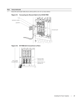
www.dell.com | support.dell.com WARNING: Prevent exposure and contact with hazardous voltages. Do not attempt to operate this system without the AC-cord Retainer. • Your power cables connect to an appropriate AC power supply in a manner that complies with your local electrical codes. For AC systems, a Main Disconnect must be provided for each AC cord. • Two fan trays are installed. To test the power supplies and fan trays: Step Task 1 With the fan trays and power supplies installed, power on the system. • Flip the On/Standby switch located next to plug AC-0 to the ON position (down). 2 Power Supply Status LEDs should be green. If an LED is not lit or is blinking amber: • check that the units are properly installed and are plugged into the correct slot. • Verify the power source • If the LED remains unlit or blinking amber at power up, replace the power supply. 3 Both fan tray LEDs should be green (online). A blinking green fan tray LED indicates booting. Verify that air is flowing through the chassis. If a fan tray is not operating properly or air is not flowing through the chassis: • power off the chassis at the remote power source. • Ensure that all fan trays are properly installed. • Verify the remote power source. • If a fan tray LED remains unlit, replace the fan tray. 4 After you have verified the power and fan operability, power off the chassis to continue the installation process. 5 De-energize the Main Disconnect and flip the On-Off switch to the OFF position. 6 Verify that the LEDs are not lit. Power Supply and Fan Tray LEDs Table 7-1. Power Supply LEDs Status No AC power Operational (On/Standby switch may be set to Standby) Power Supply Failure LED is ... Unlit: No connection Lit: GREEN Lit: AMBER Table 7-2. Fan Tray LEDs Status Booting Fault Detected Communication Failure Operational Loss of Power LED is ... Blinking: GREEN Lit: YELLOW Blinking: YELLOW Lit: GREEN Unlit 32 | Installing AC Power Supplies
-
 1
1 -
2
-
3
-
4
-
5
-
6
-
7
-
8
-
9
-
10
-
11
-
12
-
13
-
14
-
15
-
16
-
17
-
18
-
19
-
20
-
21
-
22
-
23
-
24
-
25
-
26
-
 27
27 -
 28
28 -
 29
29 -
 30
30 -
 31
31 -
 32
32 -
 33
33 -
 34
34 -
 35
35 -
 36
36 -
 37
37 -
38
-
39
-
40
-
41
-
42
-
43
-
44
-
45
-
46
-
47
-
48
-
49
-
50
-
51
-
52
-
53
-
54
-
55
-
56
-
57
-
58
-
59
-
60
-
61
-
62
-
63
-
64
-
65
-
66
-
67
-
68
-
69
-
70
-
71
-
72
-
73
-
74
-
75
-
76
-
77
-
78
-
79
-
80
-
81
-
82
-
83
-
84
-
85
-
86
-
87
-
88
-
89
-
90
-
91
-
92
-
93
-
94
 |
 |
