Dell Force10 E1200i Installing and Maintaining the E1200i System - Page 57
Removing and Replacing Components
 |
View all Dell Force10 E1200i manuals
Add to My Manuals
Save this manual to your list of manuals |
Page 57 highlights
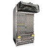
12 Removing and Replacing Components This chapter provides instructions for removing and replacing E1200 AC and DC components. It covers the following topics: • Removing and Replacing Fan Trays • Removing and Replacing AC Power Supplies • Removing and Replacing DC Power Supplies • Removing and Replacing RPMs, Line Cards, or SFMs • Removing and Replacing the Air Filter When a component fails, the E1200 system triggers major or minor alarm LEDs (located on the RPM), sends events to the SNMP trap and show alarms table, disables or changes component Status LEDs or triggers an audible alarm. Refer to Appendix C, Alarms, on page 75 for more information on alarms. Removing and Replacing Fan Trays In the event of a fan tray failure, signified by an amber LED, an SNMP trap, or major alarm event, the entire fan tray must be replaced. If one or more fans within a fan tray fail, the system generates a minor alarm and an SNMP trap. The fan trays are hot-swappable. To remove and replace the fan tray, you must have access to the rear of the chassis and be able to pull the fan tray completely out of the slot (at least 20 inches). To remove and replace a fan tray: Step Task 1 Prior to removing a fan tray, turn the screw latch counter-clockwise (with a flathead screwdriver) one quarter of a turn to unlock the fan tray. (Figure 12-1). 2 Grip the handle and pull the fan tray out approximately one inch from the chassis. Wait 30 seconds until the fan blades stop rotating, then remove. WARNING: Keep fingers clear of rotating fan blades. 3 Prior to inserting a new fan tray, fully turn (with a flathead screwdriver) the screw latch counter-clockwise until the fan tray latching mechanism retracts into the fan tray. 4 Insert the fan tray into the chassis. Guide the tray firmly into the slot until it stops and the handle end is flush with the chassis rear. 5 To secure the fan trays into place, turn the screw latch clockwise to tighten the latching mechanism. (see Figure 12-1) Removing and Replacing Components | 57
-
 1
1 -
2
-
3
-
4
-
5
-
6
-
7
-
8
-
9
-
10
-
11
-
12
-
13
-
14
-
15
-
16
-
17
-
18
-
19
-
20
-
21
-
22
-
23
-
24
-
25
-
26
-
27
-
28
-
29
-
30
-
31
-
32
-
33
-
34
-
35
-
36
-
37
-
38
-
39
-
40
-
41
-
42
-
43
-
44
-
45
-
46
-
47
-
48
-
49
-
50
-
51
-
 52
52 -
 53
53 -
 54
54 -
 55
55 -
 56
56 -
 57
57 -
 58
58 -
 59
59 -
 60
60 -
 61
61 -
 62
62 -
63
-
64
-
65
-
66
-
67
-
68
-
69
-
70
-
71
-
72
-
73
-
74
-
75
-
76
-
77
-
78
-
79
-
80
-
81
-
82
-
83
-
84
-
85
-
86
-
87
-
88
-
89
-
90
-
91
-
92
-
93
-
94
 |
 |
