Dell Force10 E1200i Installing and Maintaining the E1200i System - Page 9
The E1200 System, Operating Overview
 |
View all Dell Force10 E1200i manuals
Add to My Manuals
Save this manual to your list of manuals |
Page 9 highlights
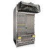
2 The E1200 System The Dell Force10 E1200 system is a carrier-class, high-capacity aggregation router. The 16-slot modular system provides two slots dedicated for Route Processor Modules (RPMs) and 14 slots for line cards with Layer 2 switching and Layer 3 and routing capabilities. Operating Overview The E1200 system requires a Route Processor Module (RPM), at least one line card, and at least eight Switch Fabric Modules (SFMs) for packet processing. The RPM is the core for routing and control operations; all traffic destined to the E1200i terminates on the RPM. Routing table entries are built on the RPM and directed to the forwarding information tables on the line cards. Software processes, such as Telnet, SNMP, CLI, Layer 2, and Layer 3 functions, are divided among three CPUs for redundancy and speed. Independent software images run on each CPU. Each CPU has its own memory, which isolates processes from each other, increasing reliability. Operating the E1200 system with redundant RPMs enables automatic fail-over redundancy. Line cards perform all data forwarding operations. Each line card has Dell Force10 proprietary ASICs - the flexible packet classification (FPC) ASIC and the Buffer and Traffic Manager (BTM) ASIC. The FPC accepts packets, feeds packets to input/output ports, handles packet classification (access lists, and Layer 2 and Layer 3 lookups), and packet-marking (Diffserv or 802.1p). The BTM is responsible for all queuing operations. The internal flash memory device shipped with the RPM contains the boot ROM and runtime images. Each RPM accommodates an external flash memory card that can be used to copy and store system boot, software images, and configuration files. For information about using a flash card, refer to Appendix A, Using a Flash Memory Card, on page 65. The E1200 System | 9
-
 1
1 -
2
-
3
-
 4
4 -
 5
5 -
 6
6 -
 7
7 -
 8
8 -
 9
9 -
 10
10 -
 11
11 -
 12
12 -
 13
13 -
 14
14 -
15
-
16
-
17
-
18
-
19
-
20
-
21
-
22
-
23
-
24
-
25
-
26
-
27
-
28
-
29
-
30
-
31
-
32
-
33
-
34
-
35
-
36
-
37
-
38
-
39
-
40
-
41
-
42
-
43
-
44
-
45
-
46
-
47
-
48
-
49
-
50
-
51
-
52
-
53
-
54
-
55
-
56
-
57
-
58
-
59
-
60
-
61
-
62
-
63
-
64
-
65
-
66
-
67
-
68
-
69
-
70
-
71
-
72
-
73
-
74
-
75
-
76
-
77
-
78
-
79
-
80
-
81
-
82
-
83
-
84
-
85
-
86
-
87
-
88
-
89
-
90
-
91
-
92
-
93
-
94
 |
 |
