Dell Force10 E1200i Installing and Maintaining the E1200i System - Page 41
Installing RPMs, Line Cards, and SFMs, Unpacking an RPM or Line Card, Important Points to Remember
 |
View all Dell Force10 E1200i manuals
Add to My Manuals
Save this manual to your list of manuals |
Page 41 highlights
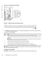
9 Installing RPMs, Line Cards, and SFMs This chapter provides instructions for installing cards into the E1200 AC or DC chassis. It contains the following sections: • Unpacking an RPM or Line Card • Installing Line Cards and RPMs • Preparing and Installing RPMs and Line Cards • RPM Label and LEDs • Installing Switch Fabric Modules (SFMs) • Line Card Cable Management Systems Unpacking an RPM or Line Card WARNING: • Electrostatic discharge (ESD) damage can occur when components are mishandled. Always wear an ESD-preventive wrist or foot-heel ground strap when handling RPMs, SFMs, or line cards. Connect your ESD strap to the grounding plug located on the front of the chassis. See Figure 2-2 for ESD strap connector location. After you remove the original packaging, place RPMs, SFMs, and line cards on an antistatic surface. • Electrostatic discharge (ESD) damage can occur when components are mishandled. Always wear an ESD-preventive wrist or foot-heel ground strap when handling RPMs, SFMs, or line cards. After you remove the original packaging, place RPMs, SFMs, and line cards on an antistatic surface. • Do not supply power to your E1200 system until the power supplies and fan tray(s) are installed and verified, and RPMs, SFMs, line cards, and any blank panels are installed. Dell Force10 recommends that you keep all components in the original packaging until you are ready to install them. Important Points to Remember • Do NOT remove the cards from their protective bags until you are ready to install them in a chassis. • When you are ready to install the cards, unwrap and install one card at a time, starting with the rightmost slot (Slot 13 for line cards, Slot R1 for RPMs, and Slot 9 for SFMs) ending with the left-most slot (Slot 0 for line cards, Slot R0 for RPMs, and Slot 0 for SFMs). • When you are ready to install the cards, unwrap and install one card at a time, starting with the right most slot (Slot R1 for RPMs and line cards, SFM Slot 2, Slot 5 or Slot 8 for SFMs) ending with the left most slot (Slot 0 for line cards, and SFM Slot 0, Slot 3 or Slot 6 for SFMs) Installing RPMs, Line Cards, and SFMs | 41
-
 1
1 -
2
-
3
-
4
-
5
-
6
-
7
-
8
-
9
-
10
-
11
-
12
-
13
-
14
-
15
-
16
-
17
-
18
-
19
-
20
-
21
-
22
-
23
-
24
-
25
-
26
-
27
-
28
-
29
-
30
-
31
-
32
-
33
-
34
-
35
-
 36
36 -
 37
37 -
 38
38 -
 39
39 -
 40
40 -
 41
41 -
 42
42 -
 43
43 -
 44
44 -
 45
45 -
 46
46 -
47
-
48
-
49
-
50
-
51
-
52
-
53
-
54
-
55
-
56
-
57
-
58
-
59
-
60
-
61
-
62
-
63
-
64
-
65
-
66
-
67
-
68
-
69
-
70
-
71
-
72
-
73
-
74
-
75
-
76
-
77
-
78
-
79
-
80
-
81
-
82
-
83
-
84
-
85
-
86
-
87
-
88
-
89
-
90
-
91
-
92
-
93
-
94
 |
 |
