Dell Force10 E1200i Installing and Maintaining the E1200i System - Page 33
Installing DC Power Supplies
 |
View all Dell Force10 E1200i manuals
Add to My Manuals
Save this manual to your list of manuals |
Page 33 highlights
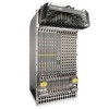
8 Installing DC Power Supplies The E1200 system requires a minimum of one DC Power Entry Module (PEM) to operate, but two are recommended for redundancy. To comply with safety agency and EMI regulations, you must install covers on all power supply slots not containing a PEM. Connect the PEMs to the appropriate branch circuit protection as defined by local electrical codes. For full redundancy, each PEM must be attached to an independent power source with a dedicated circuit breaker. For example, the PEM in slot 0 connects to circuit breaker A and the PEM in slot 1 connects to circuit breaker B. The E1200 chassis contains two DC PEM slots, as shown in Figure 8-1. Figure 8-1. PEM 0 and PEM 1 Chassis Locations PEM 0 21 21 21 21 21 21 21 21 21 21 21 21 21 21 22 22 22 22 22 22 22 22 22 22 22 22 22 22 23 RP4L-RPMC Force10 Networks 23 RP4L-RPMC Force10 Networks 23 RP4L-RPMC Force10 Networks 23 RP4L-RPMC Force10 Networks 23 RP4L-RPMC Force10 Networks 23 RP4L-RPMC Force10 Networks 23 RP4L-RPMC Force10 Networks PRIMARY RP4L-RPMC Force10 Networks PRIMARY RP4L-RPMC Force10 Networks 23 RP4L-RPMC Force10 Networks 23 RP4L-RPMC Force10 Networks 23 RP4L-RPMC Force10 Networks 23 RP4L-RPMC Force10 Networks 23 RP4L-RPMC Force10 Networks 23 RP4L-RPMC Force10 Networks 23 RP4L-RPMC Force10 Networks online fail online fail online fail online fail online fail online fail online fail online fail reset online fail reset online fail online fail online fail online fail online fail online fail online fail online fail online fail SF4L-SFMC Force10 Networks SF4L-SFMC SF4L-SFMC SF4L-SFMC SF4L-SFMC SF4L-SFMC SF4L-SFMC SF4L-SFMC SF4L-SFMC SF4L-SFMC Force10 Networks Force10 Networks Force10 Networks Force10 Networks Force10 Networks Force10 Networks Force10 Networks Force10 Networks Force10 Networks online fail online fail online fail online fail online fail online fail online fail online fail online fail online fail PEM 1 FN00100lp The DC PEM shown in Figure 8-2 is used in both the E1200 and E1200i DC chassis. Figure 8-2. E1200i DC PEM FN00101lp Installing DC Power Supplies | 33
-
 1
1 -
2
-
3
-
4
-
5
-
6
-
7
-
8
-
9
-
10
-
11
-
12
-
13
-
14
-
15
-
16
-
17
-
18
-
19
-
20
-
21
-
22
-
23
-
24
-
25
-
26
-
27
-
 28
28 -
 29
29 -
 30
30 -
 31
31 -
 32
32 -
 33
33 -
 34
34 -
 35
35 -
 36
36 -
 37
37 -
 38
38 -
39
-
40
-
41
-
42
-
43
-
44
-
45
-
46
-
47
-
48
-
49
-
50
-
51
-
52
-
53
-
54
-
55
-
56
-
57
-
58
-
59
-
60
-
61
-
62
-
63
-
64
-
65
-
66
-
67
-
68
-
69
-
70
-
71
-
72
-
73
-
74
-
75
-
76
-
77
-
78
-
79
-
80
-
81
-
82
-
83
-
84
-
85
-
86
-
87
-
88
-
89
-
90
-
91
-
92
-
93
-
94
 |
 |
