Dell Force10 E1200i Installing and Maintaining the E1200i System - Page 31
AC Power Supply and Fan Operability Test, US 220: NEMA 6-20, L6-20, L6-30 30A
 |
View all Dell Force10 E1200i manuals
Add to My Manuals
Save this manual to your list of manuals |
Page 31 highlights
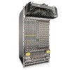
• US: C14, C20 • US 220: NEMA 6-20, L6-20, L6-30 (30A) CAUTION: The power cord is the main power disconnect device; ensure that the socket-outlet is located/ installed near the equipment and is easily accessible. Step Task 1 Make sure that the On/Standby switch, located on the left side of plug AC-0, is in the Standby (up) position (Figure 7-1). 2 Loosen the cord retainers locking screws (if needed) and tilt the AC-cord retainer up approximately 15o and gently slide the cover away from the chassis. 3 Slide the power supplies into their slots until the module front is flush with the shelf front. Figure 7-3. Insert power supply 4 Connect the Power Supply cord to the designated socket (Figure 7-1). 5 Re-install the AC-cord Retainer by tilting approximately 15o and gently sliding in the long edge just above the AC cords. 6 Secure the retainer by tighten the locking screws on either side of the retainer. WARNING: Leakage Current (High Touch Current) in AC-powered systems: AC power cords are secured to the power inlet using the provided brackets. The power cord plugs must be secured to the building outlets by the qualified chassis installer or a qualified electrician. AC Power Supply and Fan Operability Test Once your power supplies and fan trays are installed, verify their operability by supplying power to the chassis and verifying the status LEDs. Before you begin this power test, inspect your equipment rack and chassis. Verify that: • Each Power Supply is properly installed and plugged into the assigned slot. • The AC-cord Retainer is secured over the plugs. Installing AC Power Supplies | 31
-
 1
1 -
2
-
3
-
4
-
5
-
6
-
7
-
8
-
9
-
10
-
11
-
12
-
13
-
14
-
15
-
16
-
17
-
18
-
19
-
20
-
21
-
22
-
23
-
24
-
25
-
 26
26 -
 27
27 -
 28
28 -
 29
29 -
 30
30 -
 31
31 -
 32
32 -
 33
33 -
 34
34 -
 35
35 -
 36
36 -
37
-
38
-
39
-
40
-
41
-
42
-
43
-
44
-
45
-
46
-
47
-
48
-
49
-
50
-
51
-
52
-
53
-
54
-
55
-
56
-
57
-
58
-
59
-
60
-
61
-
62
-
63
-
64
-
65
-
66
-
67
-
68
-
69
-
70
-
71
-
72
-
73
-
74
-
75
-
76
-
77
-
78
-
79
-
80
-
81
-
82
-
83
-
84
-
85
-
86
-
87
-
88
-
89
-
90
-
91
-
92
-
93
-
94
 |
 |
