Dell Force10 E1200i Installing and Maintaining the E1200i System - Page 62
Removing and Replacing SFMs, until the fan tray latching mechanism retracts into the fan tray.
 |
View all Dell Force10 E1200i manuals
Add to My Manuals
Save this manual to your list of manuals |
Page 62 highlights
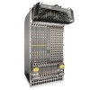
www.dell.com | support.dell.com Step Task (continued) 5 If you are installing a line card, follow these procedures: • If you are hot-swapping (replacing the line card with the same card type), no additional configuration is required. • If you are installing a different line card type, enter, in Configuration mode, the following command: linecard number card-type, where number is a slot number from 0 to 13, and card-type is the five-character code for the card type. • If you are replacing the line card with a blank panel, delete the line card information from the configuration by entering: no linecard 6 If you are not operating your system with redundant cards (with only one line card, one RPM, and eight SFMs) you must power off your system until the cards are replaced. Removing and Replacing SFMs To remove and replace an SFM: Step Task 1 Loosen the captive screw and pull the ejector lever towards you to disengage the backplane connections. 2 Slide the card out of the slot and store in the original anti-static packaging. System messages appear on the console, including the following: %TSM-6-SFM_REMOVE: Removed SFM Wait 5 to 10 seconds to install a new SFM or reinsert an SFM. * 3 Remove the new SFM from the antistatic packaging. 4 Align the new SFM with the guide and gently slide the card into the slot until you feel the connectors engage with the chassis backplane. Note: Hold the SFM by the edges. Avoid touching the printed circuit board and connector pins. Extend the card lever before you insert the card into the slot. 5 Rotate the lever to seat the backplane connectors and SFM in place. 6 Secure the SFM in place using the provided screw. 7 If you are not operating your E1200 system with redundancy, replace the empty slot with a filler panel blank. Blanks do not have board components or connector pins. Align the blank with the guides and gently slide toward the backplane. Rotate the lever to secure the blank in place. NOTE: If you mistakenly insert an SFM too quickly after removing it, traffic flow is interrupted. To correct the situation, remove an active SFM or the standby SFM, wait several seconds, and reinsert. System messages stating that the active interfaces' status changed and the switch fabric is up appear when an SFM is inserted correctly and traffic is flowing. To remove and replace a fan tray: 1 Loosen the captive screws on the fan tray with a #2 Phillips screwdriver. 2 Prior to removing a fan tray, turn the screw latch counter-clockwise (with a Phillips screwdriver) until the fan tray latching mechanism retracts into the fan tray. 3 Grip the handle and pull the fan tray halfway out from the chassis. Wait 30 seconds until the fan blades stop rotating then remove. 62 | Removing and Replacing Components
-
 1
1 -
2
-
3
-
4
-
5
-
6
-
7
-
8
-
9
-
10
-
11
-
12
-
13
-
14
-
15
-
16
-
17
-
18
-
19
-
20
-
21
-
22
-
23
-
24
-
25
-
26
-
27
-
28
-
29
-
30
-
31
-
32
-
33
-
34
-
35
-
36
-
37
-
38
-
39
-
40
-
41
-
42
-
43
-
44
-
45
-
46
-
47
-
48
-
49
-
50
-
51
-
52
-
53
-
54
-
55
-
56
-
 57
57 -
 58
58 -
 59
59 -
 60
60 -
 61
61 -
 62
62 -
 63
63 -
 64
64 -
 65
65 -
 66
66 -
 67
67 -
68
-
69
-
70
-
71
-
72
-
73
-
74
-
75
-
76
-
77
-
78
-
79
-
80
-
81
-
82
-
83
-
84
-
85
-
86
-
87
-
88
-
89
-
90
-
91
-
92
-
93
-
94
 |
 |
