Dell Force10 E1200i Installing and Maintaining the E1200i System - Page 34
Cable and Connector Requirements, Installing DC PEMs, E1200 PEM Front Panel, WARNING
 |
View all Dell Force10 E1200i manuals
Add to My Manuals
Save this manual to your list of manuals |
Page 34 highlights
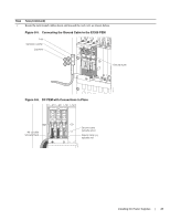
www.dell.com | support.dell.com Figure 8-3. E1200 PEM Front Panel Studs PEM interlock lever Latch Release Status -48/-60Vdc 150A, 7200VA CC-E1200-PWR-DC Over-current protector FN00102lp Locking screws Cable and Connector Requirements You must provide your own cables to connect to a remote power source (for example, a circuit breaker panel) in your equipment rack or office. Cables must be sized to meet the following criteria: • rated for at least 150A service to allow for a fully loaded E1200 system at low input voltage per your local electrical codes • limits voltage drop across the cable length to 0.5V or less Before you make the cable connections, apply a coat of antioxidant paste to un-plated metal contact surfaces. File un-plated connectors, braided straps, and bus bars to a shiny finish. It is not necessary to file and coat tinned connectors or other plated connection surfaces, such as on the E1200 PEM studs. Installing DC PEMs WARNING: An external disconnect shall be provided and shall be easily accessible. Dell Force10 recommends that you use a 150A circuit breaker. WARNING: Un interrupteur externe doit être fournis et doit êtrefacilement accessible. Dell Force10 recommande l'utilisationd'un disjoncteur de 150Ampères. WARNING: Eine leicht zugängliche Trennvorrichtung muss in der Verdrahtung eingebaut sein. Dell Force10 empfiehlt, dass Sieeinen 150A Sicherungsautomaten benutzen. Each E1200 system requires at least one load-sharing DC PEM to operate. Two units are recommended for full facility redundancy. Parameter Maximum DC PEM Input Current Maximum Power Dissipation Input Voltage Specifications 150A 6850W (21,598 BTU/hour) -48 to -60 Vdc 34 | Installing DC Power Supplies
-
 1
1 -
2
-
3
-
4
-
5
-
6
-
7
-
8
-
9
-
10
-
11
-
12
-
13
-
14
-
15
-
16
-
17
-
18
-
19
-
20
-
21
-
22
-
23
-
24
-
25
-
26
-
27
-
28
-
 29
29 -
 30
30 -
 31
31 -
 32
32 -
 33
33 -
 34
34 -
 35
35 -
 36
36 -
 37
37 -
 38
38 -
 39
39 -
40
-
41
-
42
-
43
-
44
-
45
-
46
-
47
-
48
-
49
-
50
-
51
-
52
-
53
-
54
-
55
-
56
-
57
-
58
-
59
-
60
-
61
-
62
-
63
-
64
-
65
-
66
-
67
-
68
-
69
-
70
-
71
-
72
-
73
-
74
-
75
-
76
-
77
-
78
-
79
-
80
-
81
-
82
-
83
-
84
-
85
-
86
-
87
-
88
-
89
-
90
-
91
-
92
-
93
-
94
 |
 |
