Dell Force10 E1200i Installing and Maintaining the E1200i System - Page 35
Use the following steps to install a DC PEM, PEM is fully inserted
 |
View all Dell Force10 E1200i manuals
Add to My Manuals
Save this manual to your list of manuals |
Page 35 highlights
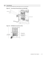
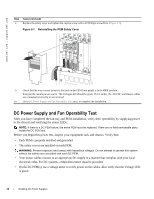
FN00103lp Use the following steps to install a DC PEM: Step Task 1 Make sure that the remote power source (the circuit breaker panel) is in the OFF position. 2 Make sure that the over-current protector (located on the PEM front panel) is in the OFF position. 3 Loosen the retaining screw and remove the PEM safety cover. R etaining s cre w S afety cover 4 Slide the PEM into the 0 or 1 slot (Figure ): Lift up and hold the PEM interlock lever and carefully push the unit inward to fully seat it to the backplane. When the PEM is fully inserted, the interlock lever will drop to hold the PEM in position. Tighten the two locking screws with a #2 Phillips screw driver to secure the PEM. Do not exceed 5 inch/lbs torque. Over current protector PEM interlock lever Locking screws Installing DC Power Supplies | 35 fn00104lp
-
 1
1 -
2
-
3
-
4
-
5
-
6
-
7
-
8
-
9
-
10
-
11
-
12
-
13
-
14
-
15
-
16
-
17
-
18
-
19
-
20
-
21
-
22
-
23
-
24
-
25
-
26
-
27
-
28
-
29
-
 30
30 -
 31
31 -
 32
32 -
 33
33 -
 34
34 -
 35
35 -
 36
36 -
 37
37 -
 38
38 -
 39
39 -
 40
40 -
41
-
42
-
43
-
44
-
45
-
46
-
47
-
48
-
49
-
50
-
51
-
52
-
53
-
54
-
55
-
56
-
57
-
58
-
59
-
60
-
61
-
62
-
63
-
64
-
65
-
66
-
67
-
68
-
69
-
70
-
71
-
72
-
73
-
74
-
75
-
76
-
77
-
78
-
79
-
80
-
81
-
82
-
83
-
84
-
85
-
86
-
87
-
88
-
89
-
90
-
91
-
92
-
93
-
94
 |
 |
