Dell Force10 E1200i Installing and Maintaining the E1200i System - Page 47
SFM Front Panel and LEDs, Line Card Cable Management Systems - price
 |
View all Dell Force10 E1200i manuals
Add to My Manuals
Save this manual to your list of manuals |
Page 47 highlights
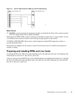
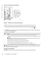
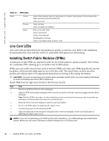
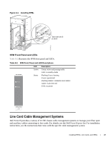
Figure 9-4. Installing SFMs Start with slot 8 or slot 9 FN00036CH SFM Front Panel and LEDs Table 9-2 illustrates the SFM front panel and LEDs. Table 9-2. SFM Front Panel and LED Descriptions CC-E-SFM3 Active Status LED Active Status Description Green: active and passing traffic Unlit: in standby mode Flashing Green: booting Green: operational Flashing Amber: communication failure Amber: fault detected Unlit: no power Switch Fabric Assy Serial Line Card Cable Management Systems Dell Force10 provides a variety of E1200 chassis cable management systems to manage your fiber optic and auxiliary cables connecting to line cards. For details, see the Dell Force10 price list. For installation instructions, see the instructions that come with the specific cable management system. Installing RPMs, Line Cards, and SFMs | 47
-
 1
1 -
2
-
3
-
4
-
5
-
6
-
7
-
8
-
9
-
10
-
11
-
12
-
13
-
14
-
15
-
16
-
17
-
18
-
19
-
20
-
21
-
22
-
23
-
24
-
25
-
26
-
27
-
28
-
29
-
30
-
31
-
32
-
33
-
34
-
35
-
36
-
37
-
38
-
39
-
40
-
41
-
 42
42 -
 43
43 -
 44
44 -
 45
45 -
 46
46 -
 47
47 -
 48
48 -
 49
49 -
 50
50 -
 51
51 -
 52
52 -
53
-
54
-
55
-
56
-
57
-
58
-
59
-
60
-
61
-
62
-
63
-
64
-
65
-
66
-
67
-
68
-
69
-
70
-
71
-
72
-
73
-
74
-
75
-
76
-
77
-
78
-
79
-
80
-
81
-
82
-
83
-
84
-
85
-
86
-
87
-
88
-
89
-
90
-
91
-
92
-
93
-
94
 |
 |
