Dell Force10 E1200i Installing and Maintaining the E1200i System - Page 38
DC Power Supply and Fan Operability Test, WARNING, Reinstalling the PEM Safety Cover
 |
View all Dell Force10 E1200i manuals
Add to My Manuals
Save this manual to your list of manuals |
Page 38 highlights
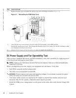
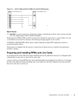
www.dell.com | support.dell.com fn00108lp Step Task (continued) 8 Replace the safety cover and tighten the captive screw with a #2 Phillips screwdriver (Figure 8-7). Figure 8-7. Reinstalling the PEM Safety Cover 9 Check that the over-current protector (located on the PEM front panel) is in the OFF position. Energize the remote power source. The Voltage LED should be green. If it is amber, the -48 VDC and Return cables are connected incorrectly or are reversed. 10 Go to DC Power Supply and Fan Operability Test, next, to complete the installation. DC Power Supply and Fan Operability Test After you have completed the fan tray and PEM installation, verify their operability by supplying power to the chassis and verifying the status LEDs. NOTE: If there is a DC PEM failure, the entire PEM must be replaced. There are no field-serviceable parts inside the DC PEM unit. Before you begin this power test, inspect your equipment rack and chassis. Verify that: • Each PEM is properly installed and grounded. • The safety covers are installed on each PEM. WARNING: Prevent exposure and contact with hazardous voltages. Do not attempt to operate this system without the safety cover provided with each DC PEM. • Your power cables connect to an appropriate DC supply in a manner that complies with your local electrical codes. For DC systems, a Main Disconnect must be provided. • On the DC PEM(s), use a voltage meter to verify power on the cables. Also verify that the Voltage LED is green. 38 | Installing DC Power Supplies
-
 1
1 -
2
-
3
-
4
-
5
-
6
-
7
-
8
-
9
-
10
-
11
-
12
-
13
-
14
-
15
-
16
-
17
-
18
-
19
-
20
-
21
-
22
-
23
-
24
-
25
-
26
-
27
-
28
-
29
-
30
-
31
-
32
-
 33
33 -
 34
34 -
 35
35 -
 36
36 -
 37
37 -
 38
38 -
 39
39 -
 40
40 -
 41
41 -
 42
42 -
 43
43 -
44
-
45
-
46
-
47
-
48
-
49
-
50
-
51
-
52
-
53
-
54
-
55
-
56
-
57
-
58
-
59
-
60
-
61
-
62
-
63
-
64
-
65
-
66
-
67
-
68
-
69
-
70
-
71
-
72
-
73
-
74
-
75
-
76
-
77
-
78
-
79
-
80
-
81
-
82
-
83
-
84
-
85
-
86
-
87
-
88
-
89
-
90
-
91
-
92
-
93
-
94
 |
 |
