Dell Force10 E1200i Installing and Maintaining the E1200i System - Page 46
Line Card LEDs, Installing Switch Fabric Modules (SFMs
 |
View all Dell Force10 E1200i manuals
Add to My Manuals
Save this manual to your list of manuals |
Page 46 highlights
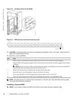
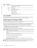
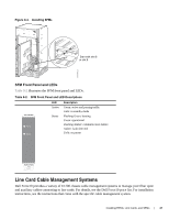
www.dell.com | support.dell.com Table 9-1. RPM LEDs Flash In Use Primary Status Green: flash memory card is in the process of a read or write process. Do not remove the flash card when the In Use LED is lit. Unlit: not in use Green: primary Unlit: secondary (or standby) This is a bi-color LED. Green: operational Amber: fault detected Flashing green: booting Unlit: in secondary mode or power is off Line Card LEDs Line card LEDs are described in the documentation specific to each line card. Refer to the installation documentation that came with the card for to understand LED appearance and meaning. Installing Switch Fabric Modules (SFMs) A minimum of eight SFMs are required in order for the E1200 system to operate properly. Slot 9 allows for a redundant SFM, allowing up to ten SFMs in the E1200i system. SFMs carry user traffic between line cards or between RPMs and a line card. SFMs plug directly into the backplane, which provides high-speed access to the line cards. The switch fabric receives user data packets and redirects them to the appropriate destinations according to the routing information. CAUTION: If you are not operating your system with a redundant (tenth) SFM, you must install an SFM blank to avoid overheating and ensure EMI containment. Install SFMs from the right-most slot (9) to the left-most slot (0). Step Task 1 Remove an SFM from the anti-static packaging. 2 Align the SFM with the guide and gently slide it into the slot until you feel the connectors engage with the chassis backplane. Note: Hold the SFM by the edges. Avoid touching the printed circuit board and connector pins. Extend the top and bottom card levers before you insert the card into the slot. 3 Rotate the lever to seat the backplane connectors and card in place. 4 Secure each SFM in place by tightening the captive screw. 5 Continue the process for the remaining SFMs. 6 Align any blank panels with the guides and gently slide toward the backplane. Secure each blank panel by tightening the single captive screw. NOTE: If you are not operating your E1200 system with redundancy, your SFM package will include blank panels. Blanks are slot covers that have no board components or connector pins. 46 | Installing RPMs, Line Cards, and SFMs
-
 1
1 -
2
-
3
-
4
-
5
-
6
-
7
-
8
-
9
-
10
-
11
-
12
-
13
-
14
-
15
-
16
-
17
-
18
-
19
-
20
-
21
-
22
-
23
-
24
-
25
-
26
-
27
-
28
-
29
-
30
-
31
-
32
-
33
-
34
-
35
-
36
-
37
-
38
-
39
-
40
-
 41
41 -
 42
42 -
 43
43 -
 44
44 -
 45
45 -
 46
46 -
 47
47 -
 48
48 -
 49
49 -
 50
50 -
 51
51 -
52
-
53
-
54
-
55
-
56
-
57
-
58
-
59
-
60
-
61
-
62
-
63
-
64
-
65
-
66
-
67
-
68
-
69
-
70
-
71
-
72
-
73
-
74
-
75
-
76
-
77
-
78
-
79
-
80
-
81
-
82
-
83
-
84
-
85
-
86
-
87
-
88
-
89
-
90
-
91
-
92
-
93
-
94
 |
 |
